
Modbus Communication Protocol 4.5
As you can see, DPS uses the Modbus RTU protocol. The Chinese firmware responds every 400ms to a Modbus request (2.5 times per second).
My alternate firmware basically uses the same Modbus registers to communicate with the DPS. Alternative firmware responds every 100ms (up to 25 times per second).
For example, U-SET can be read as holding register at address 0000H, I-SET as holding register at address 0001H, and so on.
Alternative firmware for Riden DPS and WUZHI models uses Modbus data as shown below.
In UART/USB or Bluetooth mode it works as Modbus RTU slave.
In Wi-Fi mode it works as Modbus TCP server.

You can find the communication protocol for all Riden DPS devices on the official google drive.
Modbus speed
Below in the screenshots:
- Horizontal time base 100ms per cell
- Yellow beam – Rx – request from the master
- Blue beam – Tx – response from DPS/WZ device
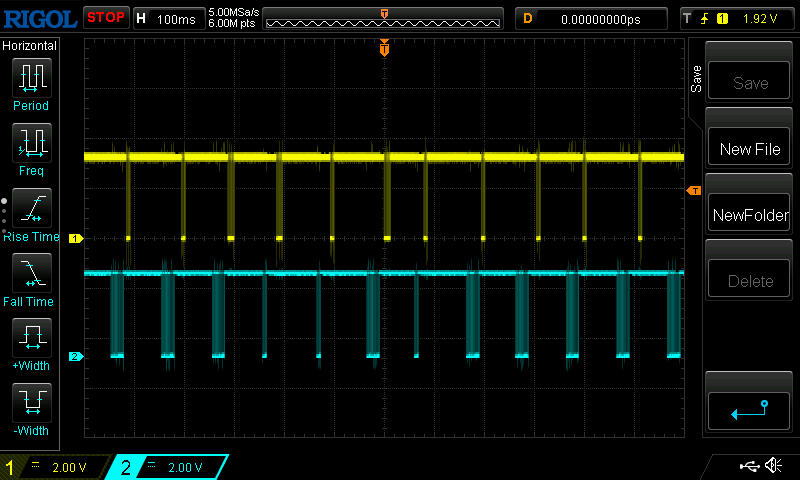
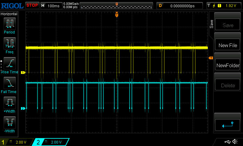
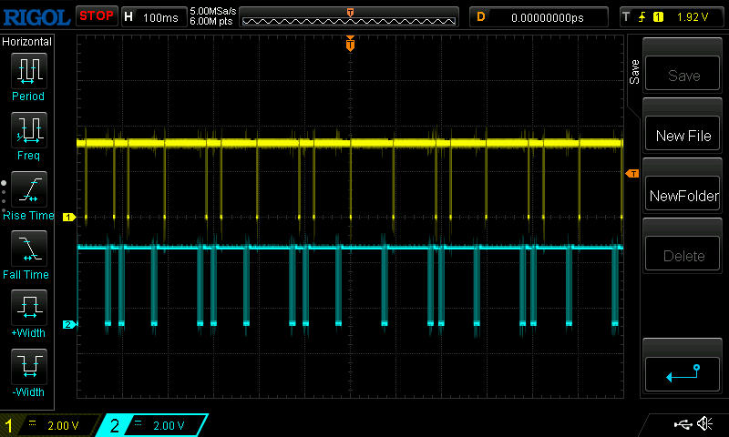

The DPS firmware cycle is 100 milliseconds. In each cycle, the firmware first sets the output values USET, ISET -> DAC. Then it measures the output values ADC -> UOUT, IOUT and the input voltage ADC -> UIN. Then it draws the screen.
After that, in the remaining time up to 100 ms, it responds to Modbus requests. How much time, so much will answer. Depending on the speed from 1 to 3 times. Thus, sending requests to write USET / ISET or read UOUT / IOUT more than once every 100 ms does not make sense.
Features of the protocol and entries in registers
In order to simultaneously control several slave devices (slaves), you can use a broadcast write request with address zero.
Executable registers are registers, when written, the DPS performs some actions:
- LOCK (7th) – manual or remote mode
- ONOFF (10th) – enable/disable output
- CMD (33rd) – see table Register CMD
- MEM (36th) – changing the profile M0 … C9
- CLB_CMD (41st) – execution of the calibration command
For the command to be executed, the write request must be a single one, not a group one !!! (except CLB_CMD).
Also, writing to some registers results in writing values to the EEPROM memory:
- CMD
- CLB_CMD
- All profile registers M0 … C9
Since the EEPROM chip has a limited life of 1 million write cycles, the programmer should avoid using these commands frequently or cyclically. To record a profile, use the group record of the USETP … OTIM registers.
Why do we need LOCK = 1 at the beginning of the session
The firmware has the function of autosaving settings for the convenience of users, so that the changes are saved the next time the device is turned on. This function saves USET, ISET and MEM values 25 seconds after the last change. However, in case of long-term control via Modbus, this feature may be detrimental. So if LOCK = 1:
Eliminates conflict with commands from device buttons
Disable autosave feature
The function of auto-detection of a connection break is launched (it works when requests from the master are not received within 2 seconds).
After the connection is broken, the device will automatically restore its LOCK = 0 and unlock the buttons.
To correctly end the session, the master must write LOCK=0 and stop transmitting.
Communication protocol ver 4.5
Communication protocol ver 4.3-4.5
| Register Addr | Name | Read / Write | Description | Range | Executable | Write to EEPROM |
|---|---|---|---|---|---|---|
| 0x0000 (0) | USET | R/W | format 00.00 | 0...Umax | ||
| 0x0001 (1) | ISET | R/W | format 00.00 or 0.000 *see STATE register | 0...Imax | ||
| 0x0002 (2) | UOUT | R | format 00.00 | |||
| 0x0003 (3) | IOUT | R | format 00.00 or 0.000 *see STATE register | |||
| 0x0004 (4) | POWER | R | format 0000.0 | |||
| 0x0005 (5) | UIN | R | format 00.00 | |||
| 0x0006 (6) | LOCK | W | Manual or remote mode. Lock-unlock keys. | 0 or 1 | YES | |
| 0x0007 (7) | PROTECT | R | *See Register PROTECT table | 0...25 | ||
| 0x0008 (8) | CVCC | R | 0 - CV, 1- CC | 0 or 1 | ||
| 0x0009 (9) | ONOFF | R/W | 0- Power off, 1- Power On | 0 or 1 | YES | |
| 0x000A (10) | BLED | R/W | LCD Backlight | 1...6 | ||
| 0x000B (11) | MODEL | R | Model | 3003...8005 | ||
| 0x000C (12) | VERSION | R | Firmware version | 18....43 | ||
| 0x000D (13) | TMP | R | Temperature in C | |||
| 0x000E (14) | STATE | R | *See STATE register below | Bitmask | ||
| 0x000F (15) | DEBUG_DATA | R | Internal use | |||
| 0x0010 (16) | MGIC | R | Internal use | |||
| 0x0011 (17) | DVID | R | Internal use | |||
| 0x0012 (18) | COMM | R | Internal use | |||
| 0x0013 (19) | GYRO | R | Internal use | |||
| 0x0014 (20) | MMAX | R/W | Max profile number | 0...19 | ||
| 0x0015 (21) | PVER | R | Protocol version ID | 43 | ||
| 0x0016 (22) | BCKL | R | Internal use | |||
| 0x0017 (23) | OHP | R/W | Overheat temperature in C | 0...200 | ||
| 0x0018 (24) | TCPL | R | Internal use | |||
| 0x0019 (25) | PARAM | R/W | *See PARAM register below | Bitmask | ||
| 0x001A (26) | MINS | R/W | minimum source battery 0% | |||
| 0x001B (27) | MAXS | R/W | maximum source battery 100% | |||
| 0x001C (28) | CLR1 | R/W | PowerOff Color | RGB565 | ||
| 0x001D (29) | CLR2 | R/W | CV color | RGB565 | ||
| 0x001E (30) | CLR3 | R/W | CC color | RGB565 | ||
| 0x001F (31) | CRC | R | Internal use | |||
| 0x0020 (32) | CMD | W | Execute command *See Register CMD table | YES | YES | |
| 0x0021 (33) | TIME_L | R | Time counter low word | |||
| 0x0022 (34) | TIME_H | R | Time counter high word | |||
| 0x0023 (35) | MEM | R/W | Profile number | 0...19 | YES | |
| 0x0024 (36) | AHCNT_L | R | Amper-hour counter low word | |||
| 0x0025 (37) | AHCNT_H | R | Amper-hour counter high word | |||
| 0x0026 (38) | WHCNT_L | R | Watt-hour counter low word | |||
| 0x0027 (39) | WHCNT_H | R | Watt-hour counter high word | |||
| 0x0028 (40) | CLB_CMD | W | *See CLB_CMD table | YES | YES | |
| 0x0029 (41) | CLB_IDX | W | *See CLB_CMD table | |||
| 0x002A (42) | CLB_DATA_L | W | Low Word for CalibRecord_t.Value | |||
| 0x002B (43) | CLB_DATA_H | W | High Word for CalibRecord_t.Value | |||
| 0x002C (44) | IP_L | R | Low Word for local IP address | |||
| 0x002D (45) | IP_H | R | High Word for local IP address |
Bitmask
STA_ANA_TEMP_SENSOR = 0x01 // Analog temperature sensor in the model
STA_DIG_TEMP_SENSOR = 0x02 // Digital temperature sensor LM75 found at startup
STA_GYRO_SENSOR = 0x04 // Optional MPU6050 gyro sensor found at startup
STA_CUR_DIV = 0x08 // Current divider is 10. Means ISET and IOUT has format 0.000
STA_MODEL_WUZHI = 0x10 //This is WUZHI
Bitmask
PARAM_C_OR_F = 0x01 // hex for 0000 0001
PARAM_RESET_COUNTERS = 0x02 // hex for 0000 0010
PARAM_SMART_DISPLAY = 0x04 // hex for 0000 0100
PARAM_BATTERY_SOURCE = 0x08 // hex for 0000 1000
PARAM_POWER_ON_START = 0x10 // hex for 0001 0000
PARAM_LOCK_ON_START = 0x20 // hex for 0010 0000
PARAM_SLEEP_ON_START = 0x40 // hex for 0100 0000
PARAM_TURN_OFF_FILTER = 0x80 // hex for 1000 0000 turn off filter for Uout, Iout, Uin
Profiles M0 ... C9
| Registers ADDR | Registers (Decimal) | Name | Write to EEPROM |
|---|---|---|---|
| 0x0050 - 0x005F | 80 - 95 | Profile M0 | YES |
| 0x0060 - 0x006F | 96 - 111 | Profile M1 | YES |
| 0x0070 - 0x007F | Profile M2 | YES | |
| 0x0080 - 0x008F | Profile M3 | YES | |
| 0x0090 - 0x009F | Profile M4 | YES | |
| 0x00A0 - 0x00AF | Profile M5 | YES | |
| 0x00B0 - 0x00BF | Profile M6 | YES | |
| 0x00C0 - 0x00CF | Profile M7 | YES | |
| 0x00D0 - 0x00DF | Profile M8 | YES | |
| 0x00E0 - 0x00EF | Profile M9 | YES | |
| 0x00F0 - 0x00FF | Profile C0 | YES | |
| 0x0100 - 0x010F | Profile C1 | YES | |
| 0x0110 - 0x011F | Profile C2 | YES | |
| 0x0120 - 0x012F | Profile C3 | YES | |
| 0x0130 - 0x013F | Profile C4 | YES | |
| 0x0140 - 0x014F | Profile C5 | YES | |
| 0x0150 - 0x015F | Profile C6 | YES | |
| 0x0160 - 0x016F | Profile C7 | YES | |
| 0x0170 - 0x017F | Profile C8 | YES | |
| 0x0180 - 0x018F | 384 - 399 | Profile C9 | YES |
Profile ver. 4.5
| Register | Name | Read \ Write | Description | Range | Firmware | Write to EEPROM |
|---|---|---|---|---|---|---|
| 0 | USETP | R /W | Uset for profile | 0...Umax | Alt / China | YES |
| 1 | ISETP | R /W | Iset for profile | 0...Imax | Alt / China | YES |
| 2 | SOVP | R /W | OVP | 0...Umax | China | YES |
| 3 | SOCP | R /W | OCP | 0...Imax | China | YES |
| 4 | SOPP | R /W | OPP | 0... Umax x Imax | Alt / China | YES |
| 5 | BLED | R /W | LCD backlight | 1...5 | China | YES |
| 6 | PRFS | R /W | *See PRFS register below | Alt | YES | |
| 7 | SINI | R /W | China | YES | ||
| 8 | OTIM | R /W | Timer value | 0...5999 | Alt | YES |
Bitmask
PROFILE_SOFT_FRONT = 0x01
PROFILE_TRIGGER_OVP = 0x02
PROFILE_TRIGGER_OCP = 0x04
PROTECT register
Error groups in the PROTECT register
- OVP…VIN – checked by DPS firmware every 100ms when the output is on.
- EPR – checked by DPS firmware when external power is applied, during the logo screen
- E16…E25 – checked by DPS firmware after calibration and each time the output is turned off.
All errors are reset when the output is turned on.
PROTECT register
| Value | Name | Description | Condition |
|---|---|---|---|
| 0 | OK | No error | |
| 1 | OVP | Overvoltage protection | Uout > Profile.OVP |
| 2 | OCP | Overcurrent protection | Iout > Profile.OCP |
| 3 | OPP | Overpower protection | Uout x Iout > Profile.OPP |
| 4 | TIM | Stopped by timer | Time > Profile.OTIM |
| 5 | OHP | Overheat protection | TMP > OHP |
| 6 | BAT | Source battery low voltage protection | Uin < MINS - 10% |
| 7 | END | Charge battery low current | Iout < 50mA for 30 seconds |
| 8 | EVP | Error voltage protection | Uset > Umax |
| 9 | ECP | Error current protection | Iset > Imax |
| 10 | VIN | Low input voltage error | Uset > Uin |
| 11 | EPR | EEPROM error | Can't read from EEPROM |
| 12 | |||
| 13 | |||
| 14 | |||
| 15 | |||
| 16 | E16 | Calibration data error | UinL >= UinH |
| 17 | E17 | Calibration data error | ADC_UinL >= ADC_UinH |
| 18 | E18 | Calibration data error | UoutL >= UoutH |
| 19 | E19 | Calibration data error | ADC_UoutL >= ADC_UoutH |
| 20 | E20 | Calibration data error | DAC_UoutL >= DAC_UoutH |
| 21 | E21 | Calibration data error | IoutL >= IoutH |
| 22 | E22 | Calibration data error | ADC_IoutL >= ADC_IoutH |
| 23 | E23 | Calibration data error | DAC_IoutL >= DAC_IoutH |
| 24 | E24 | Calibration data error | TempH Value <= 20C |
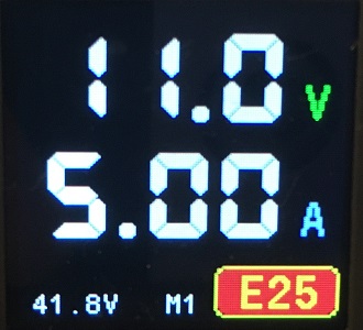
| 25 | E25 | Calibration data error | TempH ADC >= Temp ADC 20C |
Register CMD
| Value | Action |
|---|---|
| 1 | Stores MGIC ... CLR3 registers to EEPROM. Stores BLED register to EEPROM |
| 2 | Stores MEM to EEPROM Stores Profile registers to EEPOM. The profile number is in MEM register. |
| 3 | USET -> Profile.USETP ISET -> Profile.ISETP Stores MEM to EEPROM Stores Profile registers to EEPOM. The profile number is in MEM register. |
| 4 | Reset Timer and Energy counters |
| 1234 | Jump to Update Mode |
Registers CLB_CMD and CLB_IDX
| NAME=VALUE | Action/ Index |
|---|---|
| CLB_CMD = 0 | Show calibration screen |
| CLB_CMD = 1 | Start calibration for CLB_IDX |
| CLB_CMD = 2 | Fix the value in CLB_DATA for CLB_IDX |
| CLB_CMD = 3 | Exit and save calibration |
| CLB_CMD = 4 | Exit calibration w/o saving |
| CLB_IDX = 1 | U in L |
| CLB_IDX = 2 | U in H |
| CLB_IDX = 3 | U out L |
| CLB_IDX = 4 | U out H |
| CLB_IDX = 5 | I out L |
| CLB_IDX = 6 | I out H |
| CLB_IDX = 7 | Temp H |