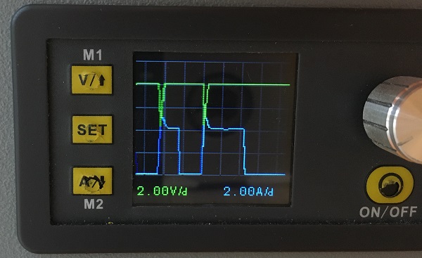
Oscilloscope page. You can see the output voltage and current in real time.
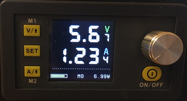
Smart and ordinary display. Smart is a 3-digit display, just like the previous version. Ordinary is a 4-digit display.
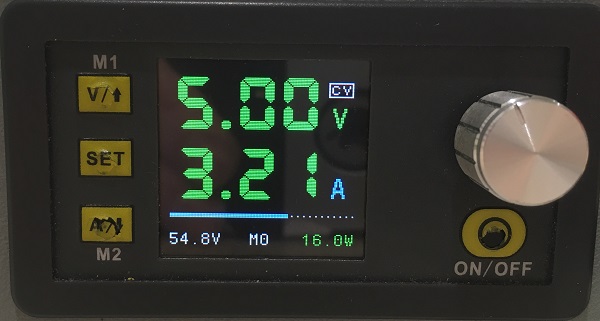
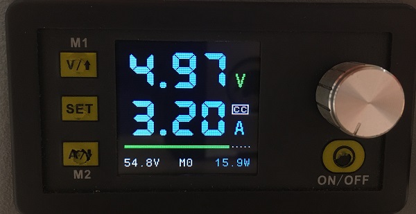
Output level indicator. On the main pages, you can see the output voltage and current in real time.
Bluetooth module debugging.
Screen rotation even without a gyroscope
Firmware update via USB/UART.
Oscilloscope
Press the “V” button to select the voltage range.
Press the “A” button to select the current range.
Press the “SET” button to select the mode:
Single voltage beam
Single current beam
Both beams. Voltage ahead
Both beams. Current ahead
Whenever the U setting or I setting is changed, the autorange function starts and changes the ranges.
Smart or Normal display
Now you can select between 3-digit or 4-digit display.
Go to “Parameters” menu, the item “Smart Display” to change the selection.
Output level indicator
Depending on CV or CC mode you can see the level of output:
In CV mode – The level is output current as a percentage of “I set”.
In CC mode – The level is output voltage as a percentage of “U set”.
In CV mode you can see the output current percentage
In CC mode you can see the output voltage percentage
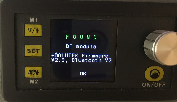
Bluetooth module debugging
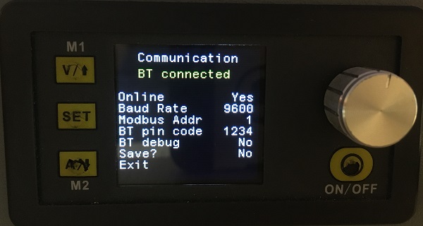
Press “Arrow Up” button after enabling power during the logo screen to enter the “Communication” menu.
If everything is OK with the bluetooth module, you will see its version.
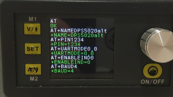
The “BT Debug” menu item allows you to see the AT command passed to the BT module. Whites are commands and greens are answers.
Communication menu
BT debug with BOLUTEK module
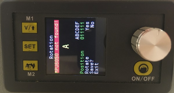
Screen rotation
Now this option works without an optional gyroscope sensor.
Press “Arrow Down” button after enabling power during the logo screen to enter the “Rotation” menu.
Set ” Rotate” to ” Yes”.
Then go to “Position” menu item and select the rotation.
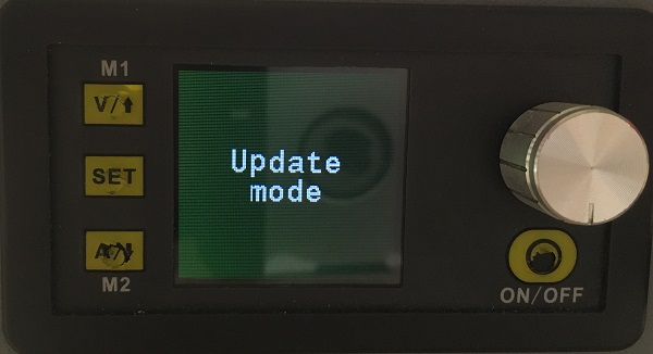
Firmware Update via USB/UART
Press “ON/OFF” button after enabling power during the logo screen to enter the “Update mode”.
When the screen goes black, you can upload new firmware using STM32CubeProgrammer (or ST’s old Flasher).
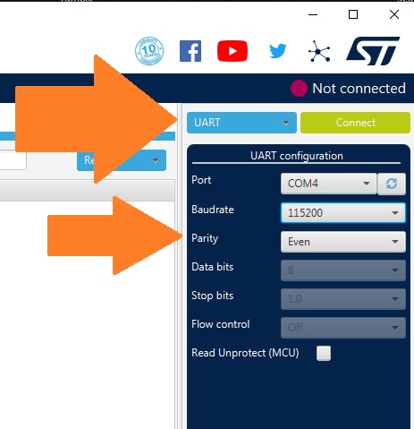
Connect USB cable to PC, start STM32CubeProgrammer, select UART, then correct COM port (any baudrate, but with parity “EVEN”), click “Connect” and start programming.
NOTE: The update doesn’t work via bluetooth because your BT whistle on PC can’t transmit “EVEN ” parity.
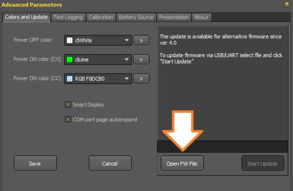
In addition, you can update the firmware to a more recent one through the DPSMaster program.
This Post Has 17 Comments
Andrey 19.02.2022
Вот прошивки через UART ждал. Не удобно каждый раз провода подсоединять. Буду следить за выходом для
Andrey 19.02.2022
DPS5015
Hardgeek95 22.02.2022
Hello, nice work!!! Great improvement, but I calibration doesn’t seem work well, after do calibration, I values are randomly put on screen when power output on without any charge
I’ll see what I can do if you send me an email to <admin@profimaxblog.ru>
Your DPS model and version with the photo of VALUE-ADC-DAC screen. Detailed description of the problem. How much the current values change, etc.
Hardgeek95 23.02.2022
Also is possible add an option to stop charging battery when I values research 10 mha o any other custom values? Will great functionality for battery charging management
Muchas gracias por este gran proyecto, acabe de instalar la versión 4 en mi DPS5005 pero al momento de hacer la calibración la corriente solo llega a 2A y cuando le doy salir y ON entra en OCP, por mas que lo calibro o modifico el OCP sigue sin encender.
Thank you very much for this great project, I just installed version 4 on my DPS5005 but at the time of calibration the current only reaches 2A and when I exit it and ON it enters OCP, no matter how much I calibrate it or modify the OCP it continues without turning on
2) Restore default settings in “Restore menu” by pushing “SET” button at startup. Let me know how it works with default settings without calibration.
Jings 16.07.2022
Hi. Thanks for making the firmware!
Just flashed my DPS5015 with version 4 (from version 3.7), and have the exact same problem as Nicolas Culma. As soon as I calibrate any of the current values (IoutL or IoutH), the current measurement fluxtuates wildly, all over the place, and I end up with a “OCP”. At this point, I’m unable to enter the calibration menu again, and have to reset the default settings. Selecting different HW revisions does not appear fix the problem, just changes the offset for the initial value. With HW revision 2.0 selected, the initial measured value for IoutL is 0.540A
This is the values with the voltages calibrated, and the current calibration untouched:
VALUE ADC DAC
5.270 3978
31.747 38271
1.006 1424 1248
26.571 32692 30640
0.100 1404 1248
5.060 12970 15008
60 160000
regards
Jings
Jings 16.07.2022
I does appear to work, if I don’t calibrate the current values:
With a a configured limit of 5V/2A, my multimeter shows 2.41A, in (shorted) current mode, and the PSU screen shows 2.35
With a a configured limit of 5V/9A, my multimeter shows 9.30A, in (shorted) current mode, and the PSU screen shows 9.37
Jings 16.07.2022
Ok, It appears that I can calibrate manually, by adjusting the parameters directly on the “VALUE-ADC-DAC page”
If I adjust these IoutL or IoutH values here, save, and then go back to the “normal” calibration menu, and check the outputs are getting closer to 0.1A / 5A, and EXIT BY POWERING OFF.
Then I repeat by adjusting on the VALUE-ADC-DAC page, until I get as close to 0.1A / 5A as possible.
The final values for IoutL or IoutH for my DPS5015 are:
0.100 1404 904
5.060 12970 14020
The final output shows:
With a a configured limit of 5V/2A, my multimeter shows 2.005A, in (shorted) current mode, and the PSU screen shows 1.93A
With a a configured limit of 5V/9A, my multimeter shows 9.000A, in (shorted) current mode, and the PSU screen shows 9.06A
Oleg 16.07.2022
Hi. “With HW revision 2.0 selected, the initial measured value for IoutL is 0.540A” So you should enter 0,540 for IoutL, then save. The next time IoutL will be closer to 0.1 amper. It does not matter if IoutL is not exactly equal 0.1 A.
Jings 17.07.2022
Yes, I know that! But if I touch any of the current calibration settings, the PSU goes completely wild, with the current measurement jumping all over the place, until it locks with an over “OCP error” after a second or two, and i have to reset it to get it usable again.
The information was provided to help profi-max diagnose the problem. I suspect (?) there is something in the calibration routine, that sets the wrong values om my model, as I was able to work around the problem by manually adjusting the values on the “VALUE-ADC-DAC page”, to calibrate the PSU
Please let me know exactly what data you enter during calibration, after which the device goes crazy. So that I can repeat your experience.
Oliver Kleinecke 15.12.2022
Hello Sir, thanks for your efforts.
I am currently running OpenDPS myself on a DPS5005 device. The reason is actually, that I want to be able to use wifi using an esp8266 (Wemos D1). Unfortunately – as the OpenDPS firmware does not support the default/stock firmware modbus protocol like yours does – tools like sigrok, which support yours and the stock firmware dps models, will not work with OpenDPS.
As I have already a finished hardware design with case and stuff, I`d be more than happy to find a software only approach to this problem.
Do you think a simple wifi to serial bridge using an esp8266 in combination with socat on linux emulating a /dev/ttySx Port would work when using your firmware? Or could a ModbusTCP to ModbusRCU bridge like e.g. this one here could work ? :
sigrok do not support ModbusTCP. But if you want to test i just build Tasmota with ModbusTCP (and Modbus MQTT) for D1 (115200, port: 502 by default) https://disk.yandex.ru/d/Eer3Mrtn_m7cLQ
Oliver Kleinecke 15.12.2022
<3 thanks for your efforts .. I`ll try to figure sth out

Вот прошивки через UART ждал. Не удобно каждый раз провода подсоединять. Буду следить за выходом для
DPS5015
Hello, nice work!!! Great improvement, but I calibration doesn’t seem work well, after do calibration, I values are randomly put on screen when power output on without any charge
Hello!
I’ll see what I can do if you send me an email to <admin@profimaxblog.ru>
Your DPS model and version with the photo of VALUE-ADC-DAC screen. Detailed description of the problem. How much the current values change, etc.
Also is possible add an option to stop charging battery when I values research 10 mha o any other custom values? Will great functionality for battery charging management
It’s a good idea.
Muchas gracias por este gran proyecto, acabe de instalar la versión 4 en mi DPS5005 pero al momento de hacer la calibración la corriente solo llega a 2A y cuando le doy salir y ON entra en OCP, por mas que lo calibro o modifico el OCP sigue sin encender.
Thank you very much for this great project, I just installed version 4 on my DPS5005 but at the time of calibration the current only reaches 2A and when I exit it and ON it enters OCP, no matter how much I calibrate it or modify the OCP it continues without turning on
Hello!
In calibration mode
IoutL current is about 0.1A and you must enter the correct value that your multimeter shows.
IoutH current is about 2.0A and you must enter the correct value that your multimeter shows.
If something goes wrong:
1) Send me the photo of the VALUE-ADC-DAC page to mail admin@profimaxblog.ru
2) Restore default settings in “Restore menu” by pushing “SET” button at startup. Let me know how it works with default settings without calibration.
Hi. Thanks for making the firmware!
Just flashed my DPS5015 with version 4 (from version 3.7), and have the exact same problem as Nicolas Culma. As soon as I calibrate any of the current values (IoutL or IoutH), the current measurement fluxtuates wildly, all over the place, and I end up with a “OCP”. At this point, I’m unable to enter the calibration menu again, and have to reset the default settings. Selecting different HW revisions does not appear fix the problem, just changes the offset for the initial value. With HW revision 2.0 selected, the initial measured value for IoutL is 0.540A
This is the values with the voltages calibrated, and the current calibration untouched:
VALUE ADC DAC
5.270 3978
31.747 38271
1.006 1424 1248
26.571 32692 30640
0.100 1404 1248
5.060 12970 15008
60 160000
regards
Jings
I does appear to work, if I don’t calibrate the current values:
With a a configured limit of 5V/2A, my multimeter shows 2.41A, in (shorted) current mode, and the PSU screen shows 2.35
With a a configured limit of 5V/9A, my multimeter shows 9.30A, in (shorted) current mode, and the PSU screen shows 9.37
Ok, It appears that I can calibrate manually, by adjusting the parameters directly on the “VALUE-ADC-DAC page”
If I adjust these IoutL or IoutH values here, save, and then go back to the “normal” calibration menu, and check the outputs are getting closer to 0.1A / 5A, and EXIT BY POWERING OFF.
Then I repeat by adjusting on the VALUE-ADC-DAC page, until I get as close to 0.1A / 5A as possible.
The final values for IoutL or IoutH for my DPS5015 are:
0.100 1404 904
5.060 12970 14020
The final output shows:
With a a configured limit of 5V/2A, my multimeter shows 2.005A, in (shorted) current mode, and the PSU screen shows 1.93A
With a a configured limit of 5V/9A, my multimeter shows 9.000A, in (shorted) current mode, and the PSU screen shows 9.06A
Hi. “With HW revision 2.0 selected, the initial measured value for IoutL is 0.540A” So you should enter 0,540 for IoutL, then save. The next time IoutL will be closer to 0.1 amper. It does not matter if IoutL is not exactly equal 0.1 A.
Yes, I know that! But if I touch any of the current calibration settings, the PSU goes completely wild, with the current measurement jumping all over the place, until it locks with an over “OCP error” after a second or two, and i have to reset it to get it usable again.
The information was provided to help profi-max diagnose the problem. I suspect (?) there is something in the calibration routine, that sets the wrong values om my model, as I was able to work around the problem by manually adjusting the values on the “VALUE-ADC-DAC page”, to calibrate the PSU
Hello!
Please let me know exactly what data you enter during calibration, after which the device goes crazy. So that I can repeat your experience.
Hello Sir, thanks for your efforts.
I am currently running OpenDPS myself on a DPS5005 device. The reason is actually, that I want to be able to use wifi using an esp8266 (Wemos D1). Unfortunately – as the OpenDPS firmware does not support the default/stock firmware modbus protocol like yours does – tools like sigrok, which support yours and the stock firmware dps models, will not work with OpenDPS.
As I have already a finished hardware design with case and stuff, I`d be more than happy to find a software only approach to this problem.
Do you think a simple wifi to serial bridge using an esp8266 in combination with socat on linux emulating a /dev/ttySx Port would work when using your firmware? Or could a ModbusTCP to ModbusRCU bridge like e.g. this one here could work ? :
https://github.com/emelianov/modbus-esp8266/blob/master/examples/Bridge/TCP-to-RTU-Simulator/TCP-to-RTU-Simulator.ino
Thanks a lot in advance and best regards,
Oliver
sigrok do not support ModbusTCP. But if you want to test i just build Tasmota with ModbusTCP (and Modbus MQTT) for D1 (115200, port: 502 by default) https://disk.yandex.ru/d/Eer3Mrtn_m7cLQ
<3 thanks for your efforts .. I`ll try to figure sth out