
Profi-Max Laboratory
Handmade Wonders
New Alternative firmware for WZ5005 and WZ6012
- Rigorous technical design.
- Large digits on the display. 3- or 4-digit display
- Ten general profiles and ten preset profiles for charging Li-Ion batteries.
- Profile setup menu.
- General parameters menu.
- Calibration menu.
- Screensaver.
- Amp and watt hour meters. Shutdown timer.
- Recovery after external power failure.
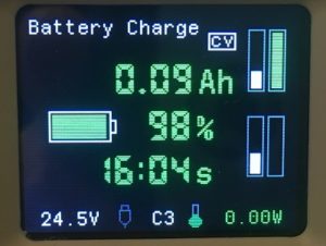
- Indication of the charge of the external power supply battery.
- Possibility of connecting additional modules: a digital thermometer with an additional fan.
- Changing the color of the indication at the user’s choice.
- Control via USB (Com-port) or Bluetooth or Wi-Fi.
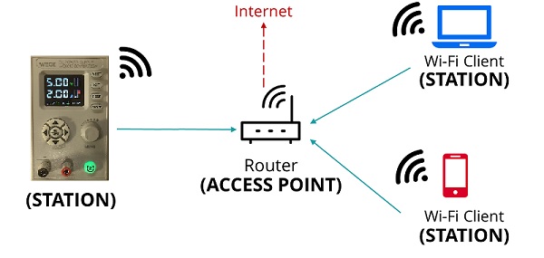
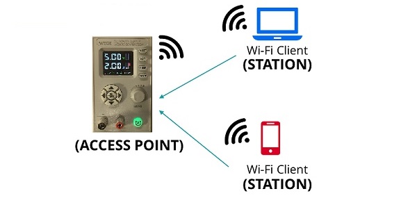
- Wi-Fi module can work as Station or Access Point.
- Firmware updates via USB/UART
- Compatible with Chinese control software (PC and Android).
- Two communication protocol: Wuzhi and RIDEN® DPS
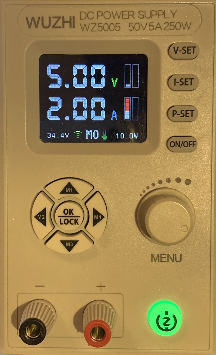
You can change the voltage and amperage after pressing buttons “V-SET” or “I-SET”. Push “P-SET” button to get into M0…C9 profile menu.
Push M1…M4 button to change the profile. You can rotate the knob while Mx indicator is flashing to select M0…C9 profiles.
- M0..M9 – general profiles.
- C0…C9 – profiles for Li-Ion battery charge.
When output is off rotate the knob to go to Parameters menu or counters pages. Navigate menu items using up and down buttons. To leave any menu without saving changes just push “ON/OFF” button.
Output power on/off
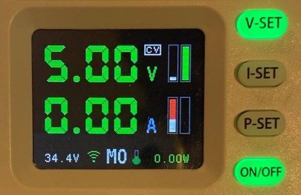
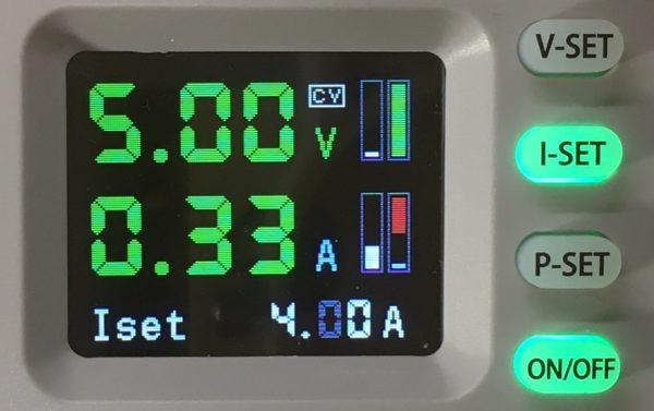
When you turn on the output power, the display color changes. CV (constant voltage) or CC (constant current) mode is displayed.
Status panel
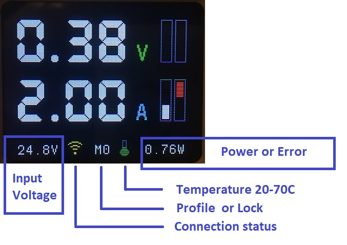
The input voltage indicator blinks if Uset > Uin.
The temperature indicator turns red at T > 50°C.
Connection status:
- GRAY USB or BT – ready to connect
- BLUE USB or BT – сonnected to host application
- GRAY Wi-Fi – not ready
- GREEN Wi-fi – ready. Station mode
- YELLOW Wi-fi – ready. Access Point mode
The indicator M0..C9 turns red when the Uset or Iset differs from those stored in the profile. Uset and Iset values are automatically stored in non-volatile memory 30 seconds after the last change.
Changing voltage and current while output is on
You can change the values after pressing buttons “V-SET” or “I-SET”.
The adjustment range is limited to avoid overvoltage.
You can’t change when the output is on:
- Profile
- Profile OVP, OCP, OPP, Timer
- Parameters
Smart or Normal display
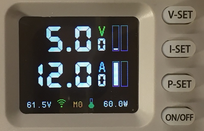
You can choose between 3-digit or 4-digit display.
Go to “Parameters” menu, the item “Smart Display” to change the selection.
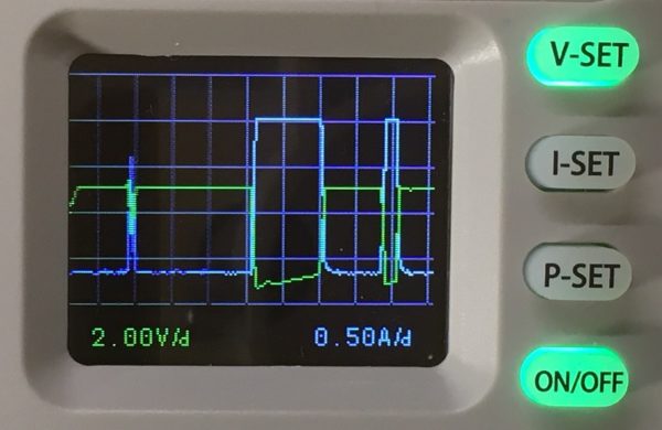
Oscilloscope
Press the “V-SET” button to select the voltage range.
Press the “I-SET” button to select the current range.
Press the “P-SET” button to select the mode:
- Single voltage beam
- Single current beam
- Both beams. Voltage ahead
- Both beams. Current ahead
Whenever the U setting or I setting is changed, the autorange function starts and changes the ranges.
Counters screen
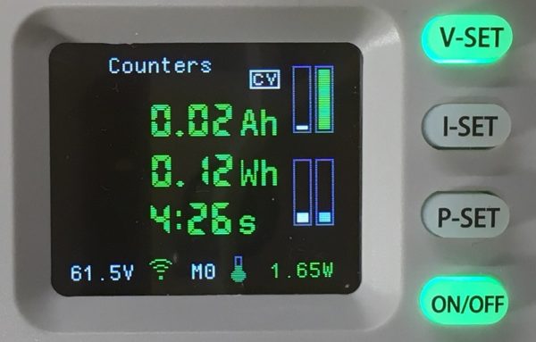
Rotate the knob to go to the counter screen.
The counters are reset every time the output is turned on, if the following is selected in the “Parameters” menu: Reset counters = Yes. Otherwise, the counters will be cumulative.
In addition, you can reset the counters by pressing the “P-SET” button for 3 seconds.
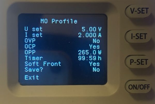
Profile setup menu (M0...M9 C0...C9)
Use the arrow buttons -up -down -left or -right to navigate through the menu items. The selected item flashes and turns green. Change the value with the knob.
If you wish to save the changes select “Save?” – Yes and then “Exit”.
To leave the menu without saving just push “ON/OFF” button.
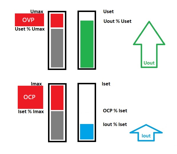
- OVP – Over Voltage Protection.
- OCP – Over Current Protection.
- OPP – Over Power Protection.
- Timer – The time in minutes of the load shutdown timer.
- Soft Front – When turned on, the voltage increases gradually.
To disable the timer, set Timer = 0.
Parameters menu
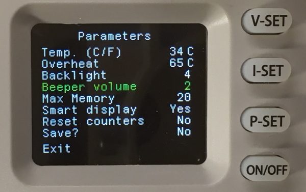
- Temp. – Tempearture and choice of Celsius or Fahrenheit.
- Overheat – The temperature when output will be turned off.
- Backlight – Screen brightness. 1 – minimum, 5 – maximum, 6 – maximum plus screensaver.
- Beeper volume – sound volume.
- Max Memory – Determines how many profiles will be available to the user.
- Smart display – Three or four digit display.
- Reset counters – Specifies the behavior of the counters. If set to Yes, the counters will be reset each time the output is turned on.
If the screensaver is activated, then five minutes after pressing the buttons, the screen brightness will decrease from maximum to minimum. The maximum brightness is restored again after any button is pressed or an error occurs.
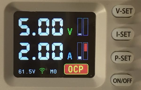
Protection
All errors are reset when the output is turned on.
- OVP – Uout > Profile.OVP (Voltage protection)
- OCP – Iout > Profile.OCP (Current protection)
- OPP – Uout x Iout > Profile.OPP (Power protection)
- TIM – Time > Profile.OTIM (Stopped by timer)
- OHP – Temperature > OHP
- BAT – Uin < MINS – 10% (Source battery low voltage protection)
- END – Iout < 50mA for 30 seconds (Charge battery low current)
- EVP – Uset > Umax (Error voltage protection)
- ECP – Iset > Imax (Error current protection)
- VIN – Uset > Uin (Low input voltage error)
- EPR – Can’t read from EEPROM
- E16 – UinL >= UinH
- E17 – ADC_UinL >= ADC_UinH
- E18 – UoutL >= UoutH
- E19 – ADC_UoutL >= ADC_UoutH
- E20 – DAC_UoutL >= DAC_UoutH
- E21 – IoutL >= IoutH
- E22 – ADC_IoutL >= ADC_IoutH
- E23 – DAC_IoutL >= DAC_IoutH
- E24 – TempH Value <= 20C
- E25 – TempH ADC >= Temp ADC 20C
Key Lock
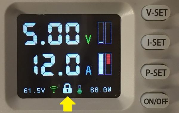
Push OK/LOCK button to lock-unlock device buttons.
NOTE: When device is connected with PC/Android application all the buttons are locked automatically and the lock turns blue.
Recovery after an external power failure
After turning on the output power with the “ON / OFF” button and then blocking the buttons by pressing the “OK/LOCK” button, the state is stored in the non-volatile memory. Thus, after an external power failure, the unit will completely restore its state.
Restore default configuration
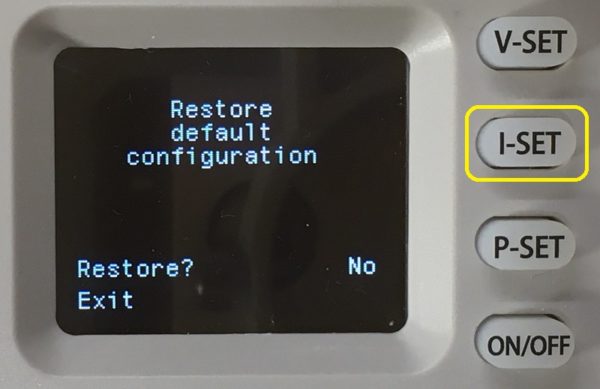
Hold “I-SET” button after power-up during the logo screen.
If you choose Restore? Yes, all memory and calibration settings will be erased and replaced with the default.
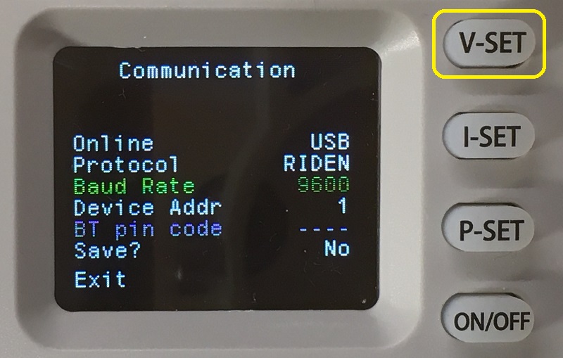
Communication menu
Hold down the “V-SET” button after turning on the power during the logo screen.
If Bluetooth is selected, the device searches for a Bluetooth connection before displaying the menu.
If Wi-Fi is selected, the device searches for a Wi-Fi connection before displaying the menu.
Turn the knob without selecting an item to enter the “Wi-Fi config” menu.
The baud rate and Modbus address must be the same as in the PC/Android app.
When you change online mode to BT or Wi-Fi, please save first. The next step will allow you other settings.
Please note: The pin code is stored in the BT module itself, not in the internal memory of the PSU.
BT connected – it means the BT board is found. Regardless of connecting to PC/Android device.
“BT Debug” starts when you save the menu in BT mode. This allows you to see the AT commands sent to the BT module. Whites are commands and greens are answers.
Select Protocol you need.
1) RIDEN to communicate with
- DPSmaster PC app (USB, BT, Wi-fi)
- Riden PC app (USB, BT)
- Riden Android app (BT)
- USB, BT – Modbus RTU Master
- Wi-Fi Modbus TCP client
2) WUZHI to communicate with
- Wuzhi PC app (USB,BT)
- Wuzhi Android app (Wi-Fi)
- Wi-Fi – TCP server
Attention: The Wi-Fi SMART config for RIDEN and WUZHI protocols are fundamentally different!
Instead of a regular one, you can use any USB-UART or UART-RS485 converters.
You can use BC-04 (or JDY-31) bluetooth modules instead of stock ones. Be careful with its supply voltage.
You can use ESP-12 modules (with ESP-8266) without prior programming instead of stock ones. Be careful with its supply voltage.
Wi-Fi config menu
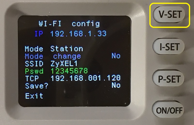
In station mode, you can connect manually by entering the SSID and password. Or you can use Wi-Fi SMART config (see below).
In access point mode, the default radio channel is 1. If you want to select a different channel (01..14), enter numbers at the beginning of the access point’s SSID. Example: 06Zyxel1 – will work on channel 06.
Hold down the “V-SET” button after turning on the power during the logo screen.
If Wi-Fi is selected, the device searches for a Wi-Fi connection before displaying the menu.
Turn the knob without selecting an item to enter the “Communication” menu.
IP – is the IP address of the device on the local wi-fi network.
Mode – Station or Access Point.
Mode change – Select “Yes” if you want to change the mode.
SSID. In station mode, this is the name of the access point you are connected to. Otherwise, the name of the access point. Maximum 16 characters.
Pswd – password. Maximum 16 characters. You cannot see the password in station mode if the Wi-Fi is already connected.
TCP – TCP server IP address for WUZHI protocol. Not used by the RIDEN protocol.
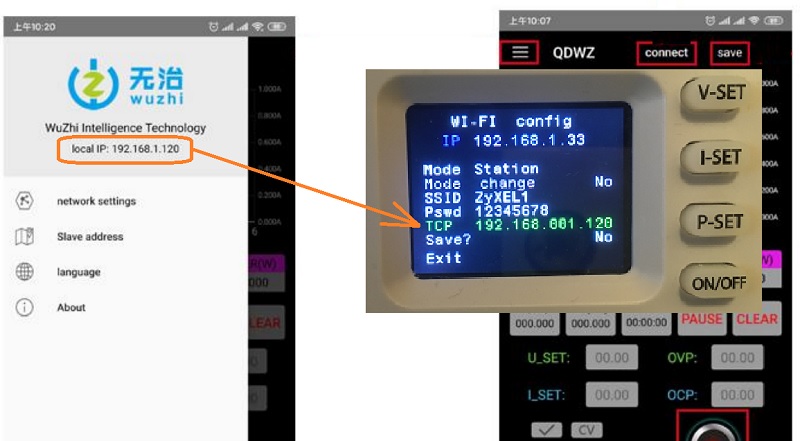
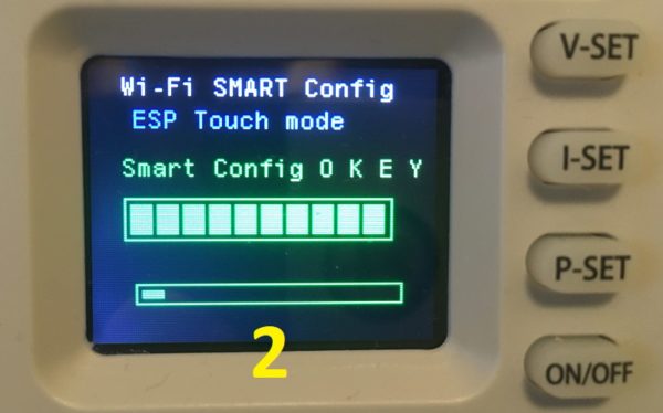
Wi-Fi SMART config - protocol WUZHI
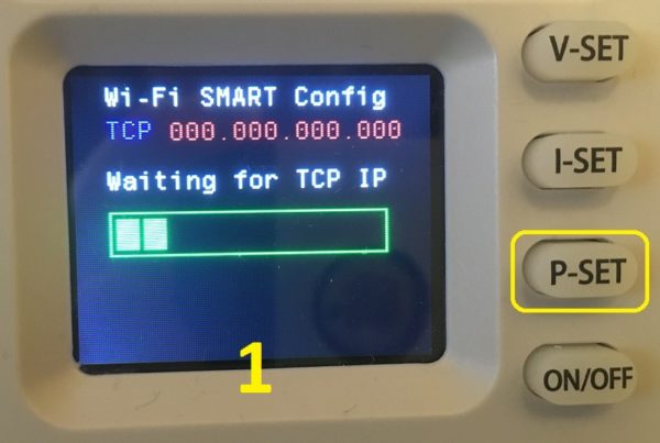
Launch android wuzhi app on your gadget. Make sure it’s connected to your local Wi-Fi network.
Hold down the “P-SET” button after turning on the power during the logo screen.
When the Wi-Fi Smart Config screen (Figure 1) appears, select “network settings” from the Android app menu.
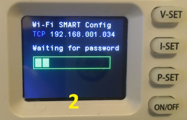
Wait for TCP to change from 000.000.000.000 to 192.168.xxx.xxx. (Figure 2)
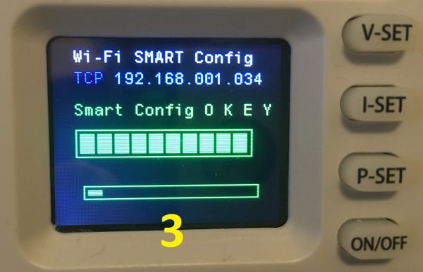
Then click “NEXT” on the Android app and enter the password for your local Wi-Fi network. Click “CONFIRM“.Wait for the SMART Config to finish (Figure 3).
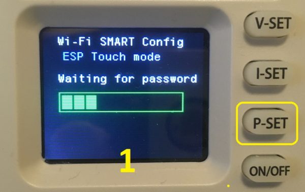
Wi-Fi SMART config - protocol RIDEN
Launch ESPTouch app on your Android or Apple gadget. Make sure it’s connected to your local Wi-Fi network. Choose “EspTouch” not “EspTouch V2”.
Enter the password for your local Wi-Fi network. Device Count = 1. Broadcast.
Hold down the “P-SET” button after turning on the power during the logo screen.
When the Wi-Fi Smart Config screen (Figure 1) appears, click “CONFIRM” in the Android app.
Wait for the SMART Config to finish (Figure 2).
Modbus communication protocol

The basic data of the communication protocol is the same as the stock Chinese protocol of DPS devices. Additional data has been added. Read more here.
Calibration
When the power output is on, press and hold “P-SET” button for 3 seconds.
The calibration procedure is pretty straightforward. You only need a multimeter and an external power supply. Do not use a load during calibration.
The basic principle of calibration is to define two points – LOW point and HIGH point. For example, we can calibrate the input voltage at 6 V (low point) and 25 V (high point). It’s enough.
The low and high points are already preset in the device, but you must enter the correct values displayed on the multimeter.
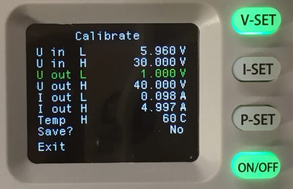
Navigate menu item by pressing arrow up and down buttons. To start item press “P-SET” button. When the item blinking set correct value by the knob. To apply the value push the rotary knob for 3 second. The applied value goes blue. To store the changes select “Save?” – Yes and then “Exit”.
To achieve greater accuracy, repeat the calibration procedure 2 or 3 times.
If something goes wrong, you can restore the default settings at any time.
NOTE. Select I out H current value suitable for the maximum current of the multimeter.
If the calibration doesn’t work – READ HERE
VALUE-ADC-DAC
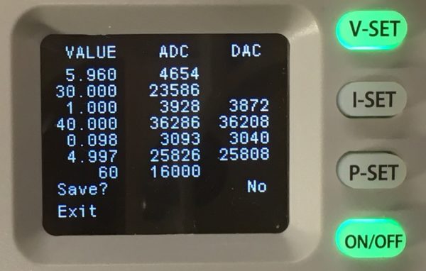
This page is mainly for information. Do not manually change the values on this page unnecessarily.
If you have a revision with a different hardware version and the calibration values differ significantly from the default ones, you can send me a photo of the VALUE-ADC-DAC page with a description of your model so that I can use your data in the next firmware revisions. admin@profimaxblog.ru
Firmware Update via USB/UART
Press “ON/OFF” button after enabling power during the logo screen to enter the “Update mode”.
When the screen goes black, you can upload new firmware using STM32CubeProgrammer (or ST’s old Flasher).
Connect USB cable to PC, start STM32CubeProgrammer, select UART, then correct COM port (baudrate 38400, with parity “EVEN“), click “Connect” and start programming.
NOTE: The update doesn’t work via bluetooth because your BT whistle on PC can’t transmit “EVEN ” parity. The update doesn’t work via Wi-Fi.
Also you can update firmware using DPSmaster application.
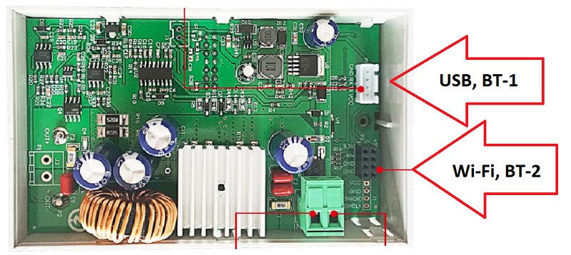
Connecting additional modules
It is possible to connect an external digital temperature sensor and an additional cooling fan.
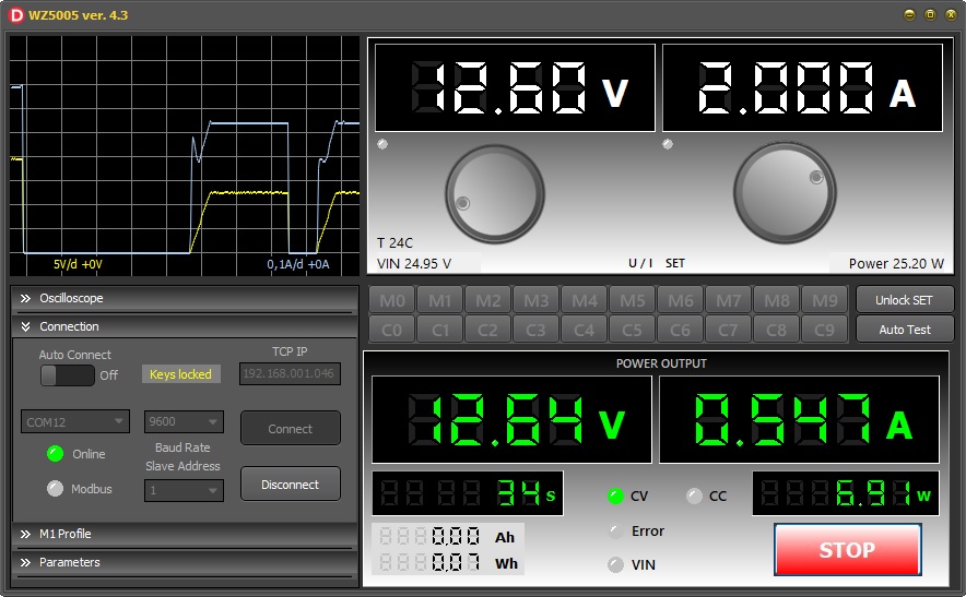
DPSmaster
DPSmaster is Windows PC application for communicate with Digital Power Suplly via USB or Bluetooth or Wi-Fi:
- WZ5005
- WZ6012
- DPS3003
- DPS3005
- DPS3012
- DPS5005
- DPS5015
- DPS5020
- DPS8005
Single application for all models. The application is 5Mb executable file without installation and any middleware. It works with stock and alternative firmware.
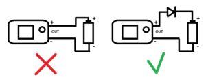
A WARNING ABOUT CHARGING BATTERIES
Connecting any rechargeable batteries directly to the output of the unit can crash the WZ device !!!
- In case of polarity reversal – 100% failure of any WZ model.
- When the output voltage of the power supply is turned off, the voltage from the battery will flow back to the power supply. This could damage it.
- These features are associated with the circuitry of the power supplies and do not depend on the firmware.
- To avoid the above charging problems, use an additional diode as shown in the figure below. Consider the amperage and voltage drop across the diode when charging.
- If you find it difficult to understand the above problems, do not charge the batteries using WZ power supplies, use specialized chargers instead.
- This topic has 53 replies, 13 voices, and was last updated 1 month, 4 weeks ago by
 profi-max.
-
AuthorPosts
-
-
19.12.2022 at 15:47 #3578profi-maxKeymaster
New alternative firmware
Rigorous technical design.
Large digits on the display. 3- or 4-digit display
Ten general profiles and ten preset profiles for charging Li-Ion batteries.
Profile setup menu.
General parameters menu.
Calibration menu.
Screensaver.
Amp and watt hour meters. Shutdown timer.
Recovery after external power failure.
Indication of the charge of the external power supply battery.
Possibility of connecting additional modules: a digital thermometer with an additional fan.
Changing the color of the indication at the user’s choice.
Control via USB (Com-port) or Bluetooth or Wi-Fi.
Wi-Fi module can work as Station or Access Point.
Firmware updates via USB/UART
Compatible with Chinese control software (PC and Android).
Two communication protocol: Wuzhi and RIDEN® DPS -
21.12.2022 at 10:14 #3642
 DoodadParticipant
Спасибо! Блин, всё так вкусно, что возникло непреодолимое желание получить эту игрушку, несмотря на то, уже имею DPS5005 с вашей прошивкой.
-
21.12.2022 at 18:11 #3651profi-maxKeymaster
Как по мне, блоки WZ намного интереснее, чем DPS. Это и размер и дизайн. Экранчик побольше и поярче. Процессор помощнее и побыстрее. Приятные мягкие кнопки с подсветкой. Звуковой сигнал. Два порта, можно например подключить сразу блютуз и усб, выбирая их из меню. И ещё эти блоки идеально помещаются в старые советские блоки питания.
Есть проблемка с пульсациями выходного напряжения, но с этим ещё не разбирался. -
22.12.2022 at 00:07 #3664EugeniyParticipant
У меня вопрос. Может STM32 софтово перегрузиться в bootloader и передать какие-то данные туда?
-
22.12.2022 at 00:56 #3665profi-maxKeymaster
>У меня вопрос. Может STM32 софтово перегрузиться в bootloader и передать какие-то данные туда?
Я не понял вопроса. Куда передать данные?
А перегрузиться программно в бутлоадер конечно можно. Что прошивка и делает, при нажатии нужных кнопок.
Через бутлоадер можно работать так-же как и через ST-Link.
Через бутлоадер можно как залить, так и прочитать прошивку. Прочитать можно, если не выставлена защита от чтения в Option Bytes.
Если защита была, её тоже можно снять через бутлоадер. Но в этом случае вся прошивка сотрется. -
22.12.2022 at 09:52 #3666EugeniyParticipant
> А перегрузиться программно в бутлоадер конечно можно.
Тогда вопрос. Зачем нам при первой прошивке ST Link? Ведь RIDEN (как уверен и остальные) имеют регистр modbus запись в который перегружает модель в bootloader mode? Можно же получается подкл UART из заводской прошивки перейти в кастом.
-
22.12.2022 at 10:19 #3667profi-maxKeymaster
>Тогда вопрос. Зачем нам при первой прошивке ST Link?
В изделиях Riden DPS3003…DPS5015…DPS8005, как и в изделиях Wuzhi WZ, никаких намёков на возможность обновления прошивки не обнаружено. Возможно там есть какая-то скрытая неопубликованная возможность, но мы об этом не знаем. В официальных опубликованных протоколах связи нет такого регистра, при записи которого происходит переход в бутлоадер.
Поэтому нам и нужен ST-Link для смены прошивки.
В своих прошивках я использую расширенный протокол связи, я дополнил протокол Riden, в том числе есть регистр при записи которого происходит переход в бутлоадер. За счет этого появилась возможность обновления прошивки.
В изделиях WZ оказалось ещё сложнее, так как там используемый стандартным бутлоадером USART1 занят вай-фаем. Пришлось писать свой собственный бутлоадер, который работает на USART3, к которому у WZ подключается адаптер USB. -
22.12.2022 at 11:19 #3668EugeniyParticipant
> В официальных опубликованных протоколах связи нет такого регистра
RIDEN
register 0x100 (value 0x1601)Для Sinilink пока не нашел, но он точно есть
-
22.12.2022 at 11:25 #3669EugeniyParticipant
RIDEN
Boot unit to bootloader mode manually: Press and hold “ENTER” button when powering on the unit. -
22.12.2022 at 12:14 #3670profi-maxKeymaster
>RIDEN
>Boot unit to bootloader mode manually: Press and hold “ENTER” button when powering on the unit.Это касается изделий Riden RD6006(P)/RD6012/RD6018. Там всё по другому, другой протокол.
Я писал про DPS3003…DPS5015…DPS8005 и Wuzhi WZ. -
22.12.2022 at 12:32 #3671EugeniyParticipant
> Там всё по другому, другой протокол.
Там другие регистры? Я думал описание протокола у них общее для всех модулей. В DPS при удержании M1 настройки порта, а при удержании SET модуль подозрительно делает паузу прежде чем загрузиться.
-
22.12.2022 at 13:01 #3672profi-maxKeymaster
Да, протоколы связи у Riden DPS и Riden RD разные. Разные регистры модбас.
-
23.12.2022 at 09:14 #3782EugeniyParticipant
Список регистров Modbus, которые использует родное приложение. Часть описана в документации, часть нет
MB_READ_DISPLAY1 = 41;
MB_READ_DISPLAY2 = 42;
MB_READ_DISPLAY3 = 43;
MB_READ_INFO = 36;
MB_READ_M = 39;
MB_READ_M0 = 45;
MB_READ_M1 = 47;
MB_READ_M2 = 49;
MB_READ_M3 = 51;
MB_READ_M4 = 53;
MB_READ_STATE = 35;
MB_READ_SYSTEM = 37;
MB_WRITE_ADDRESS = 33;
MB_WRITE_CLEAR = 114;
MB_WRITE_DISPLAY = 44;
MB_WRITE_M = 40;
MB_WRITE_M0 = 46;
MB_WRITE_M1 = 48;
MB_WRITE_M2 = 50;
MB_WRITE_M3 = 52;
MB_WRITE_M4 = 54;
MB_WRITE_MODE = 32;
MB_WRITE_POWER = 34;
MB_WRITE_PROTECT = 80;
MB_WRITE_RESET = 97;
MB_WRITE_RUN = 113;
MB_WRITE_SYSTEM = 38;
MB_WRITE_ZERO = 96; -
07.01.2023 at 18:40 #3823nopparujParticipant
Anyone have original firmware for the WZ6012 power supply and the ESP8266 wifi module?
-
10.01.2023 at 10:06 #3826ggongchiParticipant
Recently I got original firmware from WZ6012.
I shared original firmware.You need stlink and eeprom writer.
First you flashed original firmware to STM32.
And then you need to write eeprom data to 24C02N.After WZ6012 booting, you should initialize data in setting menu.
Menu name: use “reset:Y”-
This reply was modified 1 year, 3 months ago by ggongchi.
Attachments:
You must be logged in to view attached files. -
This reply was modified 1 year, 3 months ago by
-
22.01.2023 at 15:57 #3830nopparujParticipant
Thank you for the original firmware, ggongchi. May I ask you how you got the firmware? I’m interested in bypassing readout protection.
-
29.01.2023 at 06:20 #3831EngelsitParticipant
Эх….
А я постоянно заряжаю аккумулятор.
Нажимаю ON/OFF, и смотрю напряжение аккумулятора на экранчике.Иногда идут выбросы на источник питания, когда понижаю напряжение ручкой, и на блокн даже вентилятор ненадолго останавливается. Но в остальном все работает штатно. Ничего не сгорает (тьфу, тьфу), и даже не перезагружается WEGE WZ6012, то есть, питание не прерывается.
А оно точно опасно?
И да, если отключаю блок питания из розетки, получается, что он питается от аккумулятора. И даже у питающей блока питания (сорри), зелёная лампочка горит.
-
This reply was modified 1 year, 2 months ago by Engelsit.
-
This reply was modified 1 year, 2 months ago by
-
30.01.2023 at 18:22 #3833profi-maxKeymaster
Подключение АКБ напрямик к выходу – на ваш страх и риск. Может и не случится ни чего. А может случиться как тут https://youtube.com/shorts/3TZ0kz89M-o?
-
02.03.2023 at 09:54 #3849MacgotParticipant
Приветствую!
Собираюсь считывать по USB автономным логгером Uout, Iout и OnOff, какие подводные камни могут быть без включения Lock кроме отсутствия автоопределения обрыва связи?
Я правильно понимаю, если в процессе работы(заряда) я не меняю USET, ISET и MEM, то “Автосохранение” не происходит, и конфликтов с кнопками быть не должно?Why do we need LOCK = 1 at the beginning of the session – https://profimaxblog.ru/modbus-communication-protocol/
-
02.03.2023 at 12:50 #3850MacgotParticipant
И вопрос вдогонку. Почему в PC-приложениях (DPSmaster, DPS5005 PC Software) нет возможности сохранять Uout, Iout в csv, а в мобильных приложениях (DPS(H) Series Android APP и в оригинальном китайском приложении) такой функционал есть? Есть какая-то разница в связи по USB и по “воздуху”?
-
03.03.2023 at 02:04 #3851profi-maxKeymaster
Здравствуйте!
Если только считывать Uout, Iout и OnOff, то “Автосохранения” не случится и конфликта с кнопками не будет.
Обрыв связи определяется не состоянием регистра LOCK, а наличием запросов от мастера (неважно запрос на запись или чтение). Подводных камней быть не должно, если мастер посылает запрос только после того как получил ответ. Если нет возможности контролировать поступление ответа, тогда нужно делать задержку между запросами не менее 100 миллисекунд.
Я не вижу взаимосвязи между форматом лог-файла и выбором связи USB или Bluetooth.
Скорее всего есть опасность создания файла слишком большого размера.
Если на смартфоне пользователь вряд-ли будет долго вести лог, то на настольном компьютере пользователь может включить лог на несколько суток, не подозревая что создается гигантский файл, который потом будет невозможно открыть.-
This reply was modified 1 year, 1 month ago by profi-max.
-
This reply was modified 1 year, 1 month ago by
-
15.03.2023 at 19:40 #3859fredioParticipant
I love your project and want to buy a small power supply.
Is this firmware compatible with the lower spec WZ3605? -
15.03.2023 at 19:49 #3860profi-maxKeymaster
I’m not sure about WZ3605. I do not have this in my laboratory, so I can’t check it.
-
15.03.2023 at 22:56 #3861fredioParticipant
Thanks for the quick reply! I will go with the WZ5005 then.
As far as I can see Wifi should also work with an ESP01 (based on ESP8266), right?
It is the same chip just with less GPIO. -
16.03.2023 at 00:42 #3862profi-maxKeymaster
I tested working with ESP-12 (ESP8266 inside). Everything is fine. The firmware uses the AT commands implemented in the ESP8266.
-
22.03.2023 at 15:59 #3863fredioParticipant
As per Aliexpress page the WZ5005 has a current output resolution of 0.001A in the original firmware.
Would it be possible to get a third digit after the decimal point for the 4digit display? Like 3.123A instead of 3.12A -
23.03.2023 at 10:13 #3864profi-maxKeymaster
You can switch between 3 and 4 digit display. But unfortunately there is noise at the output when the resolution is 0.001
-
20.05.2023 at 19:55 #4014Corado47Participant
Hello!
You have a firmware for WZ5005E ?
Thanks! -
22.05.2023 at 07:50 #4016Corado47Participant
Thank you!
-
14.07.2023 at 23:58 #4048enache_cosmin022@yahoo.comParticipant
where is the firmware file ? i dont find the download link anywhere .
-
15.07.2023 at 05:39 #4049DoodadParticipant
Everything is on the project page. https://profimaxblog.ru/wz_fw_flashing/
WZ5005 alt firmware full ver 4.4 (16 downloads)
WZ6012 alt firmware full ver 4.4 (16 downloads)
WZ5005 alt firmware update ver 4.4 (12 downloads)
WZ6012 alt firmware update ver 4.4 (10 downloads)-
This reply was modified 9 months, 2 weeks ago by Doodad.
-
This reply was modified 9 months, 2 weeks ago by
-
-
30.08.2023 at 14:29 #4051chrizbeeParticipant
I can’t manage to connect to the ST.
Is there a way to hold the device in reset while connecting?Error: No STM32 target found! If your product embeds Debug Authentication, please perform a discovery using Debug Authentication
-
31.08.2023 at 19:21 #4052profi-maxKeymaster
Hello!
ST-Link perfectly connects with the MCU when it is in run mode. No need any reset mode.
Use external power for WZ device as usual. Do not connect power via the ST-link. Update your ST-link firmware.-
31.08.2023 at 23:09 #4056chrizbeeParticipant
>> Use external power for WZ device as usual. Do not connect power via the ST-link. Update your ST-link firmware.
I did all that – maybe the ST-Link is broken? But then it wouldn’t have been recognized by the STM32 programmer in the first place…I bought this clone from china 🙂
https://aliexpress.com/item/1005005494623572.html-
01.09.2023 at 01:16 #4057profi-maxKeymaster
Here is my st-link connection from begining till the end. Without “UR connection”, “HWrst” and so on.
Check ST-Link configuration at the right side: Port SWD, Freq 4000, etc.-
This reply was modified 7 months, 4 weeks ago by profi-max.
-
This reply was modified 7 months, 4 weeks ago by profi-max.
Attachments:
You must be logged in to view attached files.-
01.09.2023 at 10:20 #4061chrizbeeParticipant
Same as my config. I have a newer firmware and software version though.
Attachments:
You must be logged in to view attached files.-
01.09.2023 at 10:46 #4063profi-maxKeymaster
Perhaps new versions of CubeProgrammer conflict with Chinese ST-Link clones. Try to find older versions of CubeProgrammer. Or find an already proven ST-Link in your city. I’ve seen Chinese clones that don’t work at all.
-
01.09.2023 at 12:36 #4064chrizbeeParticipant
Okay, different plan…
I found a J-Link Plus laying around so I’m using that instead 🙂Can you tell me which chip exactly is used in a WZ6012 (see attached screenshot)?
Also do I need any more information?Thanks for your help!
Attachments:
You must be logged in to view attached files.
-
-
-
This reply was modified 7 months, 4 weeks ago by
-
-
-
-
26.10.2023 at 09:04 #4090chrizbeeParticipant
Silly question: Is there a special trick to open this thing up?
I want to reach the output voltage preferably from the back or from the side. -
24.02.2024 at 15:27 #4502kdh5918Participant
Hello, I am in a very difficult situation now.
6012 During uploading, an error message appeared as shown on the screen, and then the device became bricked.
What should I do? BroAttachments:
You must be logged in to view attached files.-
24.02.2024 at 15:29 #4504kdh5918Participant
Sometimes phrases like this also appear.
Error: failed to erase memory-
24.02.2024 at 17:11 #4505profi-maxKeymaster
Hello!
Select OB (option bytes) at the left panel, then uncheck RDP (Read out protection bytes), then click Apply.-
This reply was modified 2 months ago by profi-max.
-
This reply was modified 2 months ago by
-
-
-
-
AuthorPosts
- You must be logged in to reply to this topic.