
Profi-Max Laboratory
Handmade Wonders
New Alternative firmware for DPS3003... DPS5020
- Rigorous technical design.
- Large digits on the display. 3- or 4-digit display
- Ten general profiles and ten preset profiles for charging Li-Ion batteries.
- Profile setup menu.
- General parameters menu.
- Calibration menu.
- Screensaver. Screen rotation.
- Amp and watt hour meters. Shutdown timer.
- Recovery after external power failure.
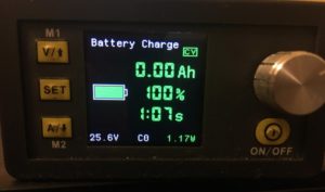
- Indication of the charge of the external power supply battery.
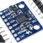
- Possibility of connecting additional modules: a gyro sensor for screen rotation and a digital thermometer with an additional fan.
- Changing the color of the indication at the user’s choice.
- Control via USB (Com-port) or Bluetooth or WiFi.
- Firmware update via USB/UART
- Compatible with Chinese control software.
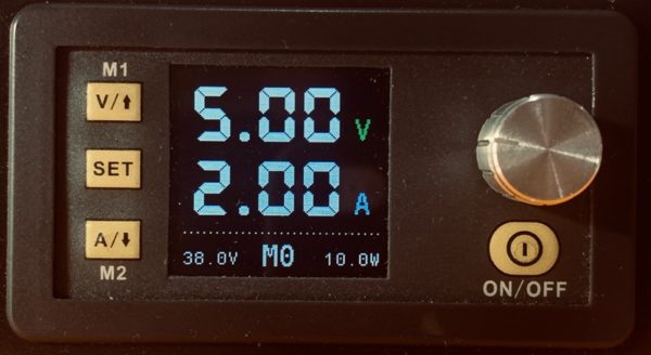
You can change the voltage and amperage after pressing buttons “V” or “A”. Rotate the knob to select menu or counters pages. Navigate menu items using up and down buttons. To leave any menu without saving changes just push “ON/OFF” button.
At the main screen push “SET” button and rotate the knob to select a profile. There are 20 profiles:
- M0..M9 – general profiles.
- C0…C9 – profiles for Li-Ion battery charge.
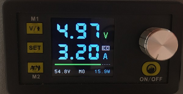
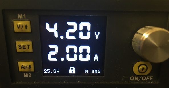
Output power on/off
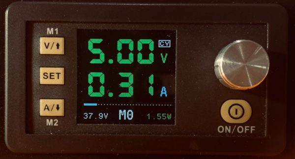
When you turn on the output power, the display color changes. CV (constant voltage) or CC (constant current) mode is displayed.
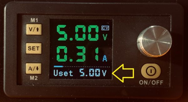
Changing voltage and current while output is on
You can change the values after pressing buttons “V” or “A”.
The adjustment range is limited to avoid overvoltage.
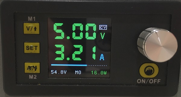
Output level indicator
Depending on CV or CC mode you can see the level of output:
- In CV mode – The level is output current as a percentage of “I set”.
- In CC mode – The level is output voltage as a percentage of “U set”.
Smart or Normal display
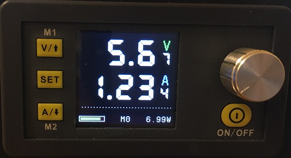
Now you can select between 3-digit or 4-digit display.
Go to “Parameters” menu, the item “Smart Display” to change the selection.
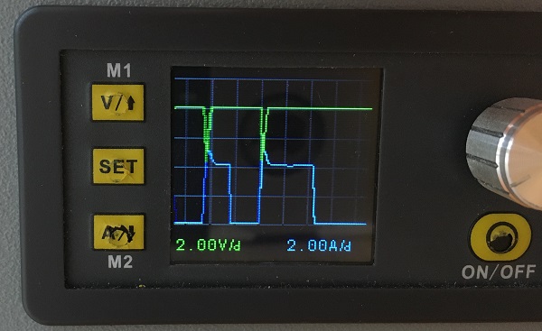
Oscilloscope
Press the “V” button to select the voltage range.
Press the “A” button to select the current range.
Press the “SET” button to select the mode:
- Single voltage beam
- Single current beam
- Both beams. Voltage ahead
- Both beams. Current ahead
Whenever the U setting or I setting is changed, the autorange function starts and changes the ranges.
Counters screen
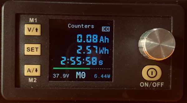
Rotate the knob to go to the counter screen.
The counters are reset every time the output is turned on, if the following is selected in the “Parameters” menu: Reset counters = Yes. Otherwise, the counters will be cumulative.
In addition, you can reset the counters by pressing the “SET” button for 3 seconds.
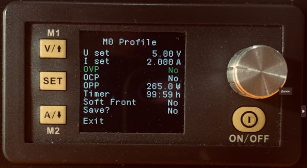
Profile setup menu (M0...M9 C0...C9)
When output is off rotate the knob to go to different menu. Use arrow-up and arrow-down buttons to navigate through menu items. The selected item is blinking and go green. Change value with the knob.
If you wish to save changes select “Save?” – Yes and then “Exit”.
To leave menu without saving just push “ON/OFF” button.
- OVP – Over Voltage Protection.
- OCP – Over Current Protection.
- OPP – Over Power Protection.
- Overtime – The time in minutes of the load shutdown timer.
- Soft Front – When turned on, the voltage increases gradually.
To disable the timer, set Overtime = 0.
Parameters menu
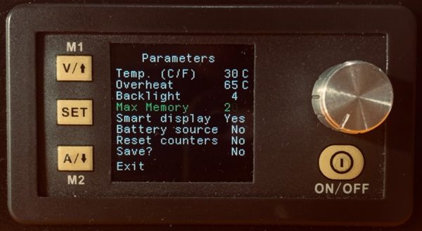
- Temp. – Tempearture and choice of Celsius or Fahrenheit.
- Overheat – The temperature when output will be turned off.
- Backlight – Screen brightness. 1 – minimum, 5 – maximum, 6 – maximum plus screensaver.
- Smart display – Three or four digit display.
- Battery source – The main page displays the state of charge of the input battery. Used for Li-ion powered mobile DPS.
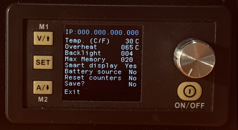
- Max Memory – Determines how many memory cells will be available to the user using the “SET” button.
- Reset counters – Specifies the behavior of the counters. If set to Yes, the counters will be reset each time the output is turned on.
If the screensaver is activated, then five minutes after pressing the buttons, the screen brightness will decrease from maximum to minimum. The maximum brightness is restored again after any button is pressed or an error occurs.
To see the current IP address on the local network:
- Go to Parameters menu
- Press the SET button
The IP address will be displayed for 3 seconds.
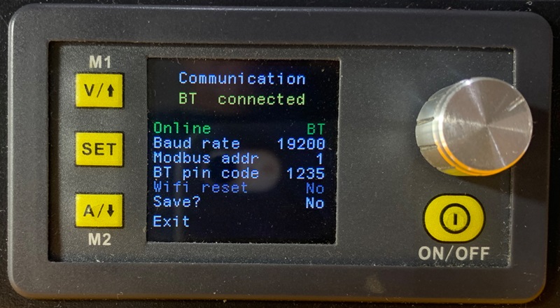
Communication menu
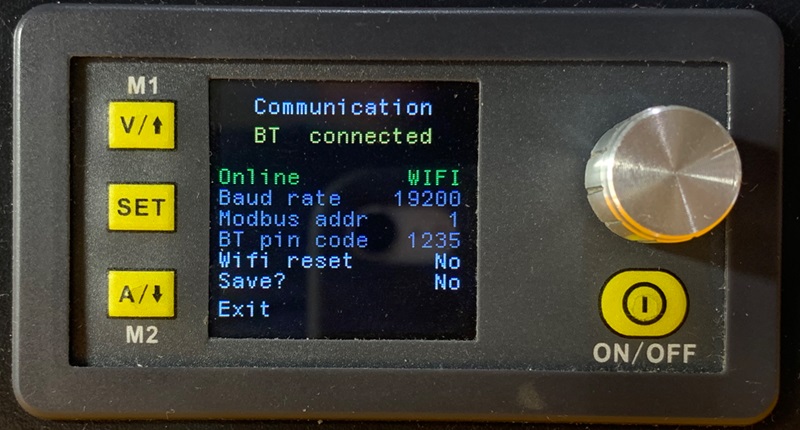
Hold the “M1” (arrow-up) button after power-on during the logo screen. For the first few seconds, the device looks for a bluetooth connection.
Baud Rate and Modbus Address should be the same as in PC/Android application.
WiFi mode makes the connection through an external ESP8266 (ESP-12) board.
WiFi reset – to connect to the router.
How to use WiFi: Read about WiFi module
Please note: The pin code is stored in the BT module itself, and not in the internal memory of the PSU.
BT connected – means BT board found. No matter connection with PC/Android device.
In BT (bluetooth) mode, you will see AT commands transmitted to the BT module. The white ones are the commands and the green ones are the answers.
Restore default configuration
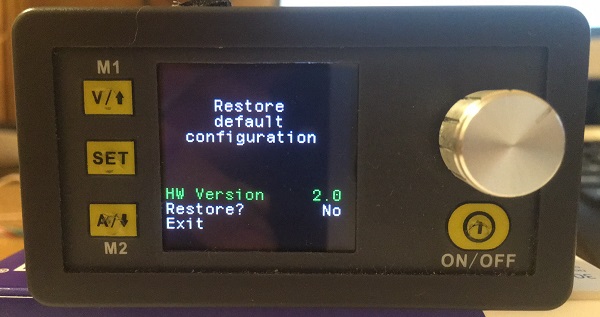
Hold “SET” button after power-on during the logo screen.
If you choose Restore? Yes, all memory and calibration settings will be erased and replaced with the default.
There is a choice of hardware version. This is necessary for various revisions of printed circuit boards for calibration to work.
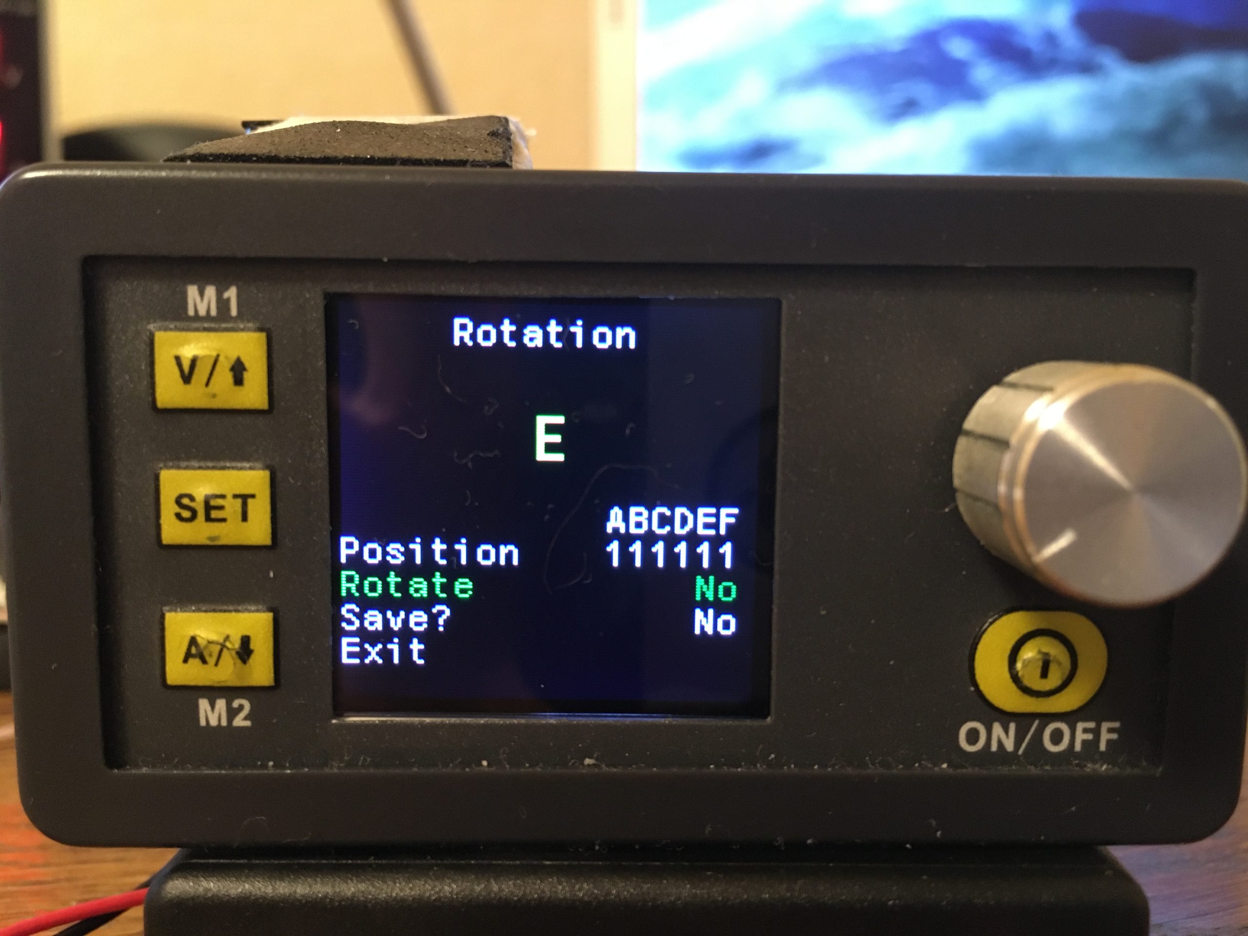
Screen rotation menu
Hold “M2” (arrow-down) button after power-on during the logo screen.
Set ” Rotate” to ” Yes”.
Then go to “Position” menu item and select the rotation.
The automatic screen rotation is available with external MPU6050 Gyroscope Sensor .
You can place the sensor in any position and then set the correct screen rotation in this menu.
Key Lock
Push rotary knob to lock-unlock device buttons.
NOTE: When device is connected with PC/Android application all the buttons are locked automatically.
Recovery after an external power failure
After turning on the output power with the “ON / OFF” button and then blocking the buttons by pressing the encoder, the state is stored in the non-volatile memory. Thus, after an external power failure, the unit will completely restore its state.
Modbus communication protocol

The basic data of the communication protocol is the same as the stock Chinese protocol of DPS devices. Additional data has been added. Read more here.
Calibration
When the power output is on, press and hold “SET” button for 3 seconds.
The calibration procedure is pretty straightforward. You only need a multimeter and an external power supply. Do not use a load during calibration.
The basic principle of calibration is to define two points – LOW point and HIGH point. For example, we can calibrate the input voltage at 6 V (low point) and 25 V (high point). It’s enough.
The low and high points are already preset in the device, but you must enter the correct values displayed on the multimeter.
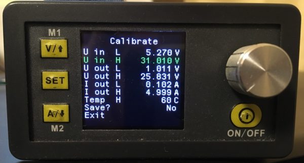
Navigate menu item by pressing arrow up and down buttons. To start item press “SET” button. When the item blinking set correct value by the knob. To apply the value push the rotary knob for 3 second. The applied value goes blue. To store the changes select “Save?” – Yes and then “Exit”.
To achieve greater accuracy, repeat the calibration procedure 2 or 3 times.
If something goes wrong, you can restore the default settings at any time.
NOTE. Select I out H current value suitable for the maximum current of the multimeter.
Video – How to calibrate in Russian
If the calibration doesn’t work – READ HERE
VALUE-ADC-DAC
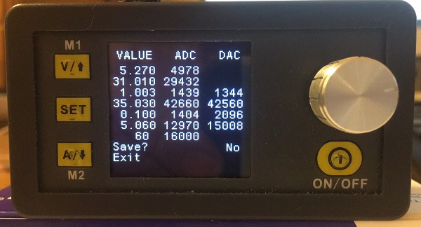
Since firmware version 3.8 a page with calibration data has been added. This page is mainly for information. Do not manually change the values on this page unnecessarily.
If you have a revision with a different hardware version and the calibration values differ significantly from the default ones, you can send me a photo of the VALUE-ADC-DAC page with a description of your model so that I can use your data in the next firmware revisions. admin@profimaxblog.ru
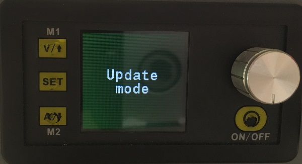
Firmware Update via USB/UART
Press “ON/OFF” button after enabling power during the logo screen to enter the “Update mode”.
When the screen goes black, you can upload new firmware using STM32CubeProgrammer (or ST’s old Flasher / or DPSmaster application).
Connect USB cable to PC, start STM32CubeProgrammer, select UART, then correct COM port (any baudrate, but with parity “EVEN”), click “Connect” and start programming.
NOTE: The update doesn’t work via bluetooth because your BT whistle on PC can’t transmit “EVEN ” parity.
Connecting additional modules
Starting with firmware version 3.6, it is possible to connect an external gyro sensor to rotate the screen.
Starting with firmware version 3.7, it is possible to connect an external digital temperature sensor and an additional cooling fan.
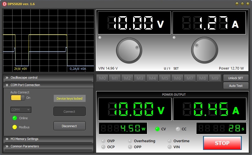
DPSmaster
DPSmaster is Windows PC application for communicate to RIDEN DPS (Digital Power Suplly) via USB or Bluetooth:
- DPS3003
- DPS3005
- DPS3012
- DPS5005
- DPS5015
- DPS5020
- DPS8005
Single application for all models. The application is 5Mb executable file without installation and any middleware. It works with stock and alternative firmware.
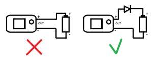
A WARNING ABOUT CHARGING BATTERIES
Connecting any rechargeable batteries directly to the output of the unit can crash the DPS device !!!
- In case of polarity reversal – 100% failure of any DPS model.
- When the output voltage of the power supply is turned off, the voltage from the battery will flow back to the power supply. This could damage it.
- These features are associated with the circuitry of the power supplies and do not depend on the firmware.
- To avoid the above charging problems, use an additional diode as shown in the figure below. Consider the amperage and voltage drop across the diode when charging.
- If you find it difficult to understand the above problems, do not charge the batteries using DPS power supplies, use specialized chargers instead.
- This topic has 117 replies, 18 voices, and was last updated 1 month, 2 weeks ago by
 profi-max.
-
AuthorPosts
-
-
19.12.2022 at 15:46 #3577profi-maxKeymaster
DPS3003 DPS3005 DPS3012 DPS5005 DPS5015 DPS5020 DPS8005
Новая прошивка версии 4.3
1)Расширенная защита.
2) Индикация автосохранения.
3) Скорость связи увеличена до 115200 бит/сек
4) Улучшена отзывчивость на запросы Modbus
5) Внесены дополнения в протокол
Подробности тут:-
This topic was modified 1 year, 7 months ago by profi-max.
-
This topic was modified 1 year, 7 months ago by
-
23.12.2022 at 14:11 #3783
 JallaaParticipant
А можно сделать прошивку под дисплей 3,5 дюйма, и распаять все кнопки и дисплей, прибор отличный, но мелкий экран и близко все кнопки.
-
23.12.2022 at 16:46 #3784profi-maxKeymaster
>А можно сделать прошивку под дисплей 3,5 дюйма, и распаять все кнопки и дисплей, прибор отличный, но мелкий экран и близко все кнопки.
В ближайшее время таких планов нет. И свободного времени тоже нет. Может быть когда-нибудь, но не факт. -
02.02.2023 at 06:23 #3834wznParticipant
DPS5020 китайская прошивка. Пользователь несколько лет.
Зарегестрировался тут, чтоб поговорить о наболевшем.
1. Три цифры индикации это мало. Использую 4 цифры (штатный экран) на ток и внешний 5 цифр на напряжение (китайский модуль 5 знаков с поверкой в Самарском центре стандартизации).
Ваши три цифры – ни о чём.
2. Использую провод 7AWG чтоб при значительном выходном токе напряжение было похоже на то, которое на экране DPS5020.
3. Практически использую только m1 и m2 настройку. 1,65 и 14,5 вольт соответственно. Остальное под текущую задачу довожу донастройкой. Остальные m настройки я просто не запоминаю (забываю).
4. В штатном комплекте почему-то графики в Еxcel удавалось сохранить только на телефон (android). Они нафиг там не нужны. Нужны в компьютере, но компьютерное ПО их не пишет. За то имеет кучу настроек самого блока ( а они нужны как раз на телефоне.
5. Совершенно неочевидное управление кнопками и ручкой при настройке. -
02.02.2023 at 07:09 #3835wznParticipant
Вспомнил ещё пару взаимосвязанных пунктов:
6. Очень неудобное расположение кнопки включения DPS5020 под энкодером. Важно, что решение этой проблемы достаточно простое – положить (или поставить) DPS5020 на бок. Так что бы выходные клеммы были снизу. При этом решается проблема с доступом к кнопке включения и уменьшается используемое место на столе. Однако,это выявляет ещё одну проблему:
7. Экран не поворачивает информацию, если расположение DPS5020 отличается от горизонтального. -
02.02.2023 at 20:44 #3836profi-maxKeymaster
С удовольствием пообсуждаю эти блоки. В режиме обмена мнениями и информацией. Разные точки зрения приветствуются)
>>>Три цифры индикации мало.
Ответ: Выбрать 4 цифры вместо 3 можно в меню “Parameters” пункт “Smart Display”. Кроме этого, задать выходное напряжение и ток с высокой точностью можно в меню профиля M0…M9 Profile, даже когда включен 3 значный режим индикации.Посчитаем теоретически возможную точность DPS5020. Установлен процессор STM32F100 который имеет 12-разрядные АЦП и ЦАП. Двенадцать разрядов – это 4096 отсчетов. Получаем теоретическую точность для напряжения: 50 вольт разделить на 4096 равно 0,012 вольт. Теоретическая точность для тока: 20 ампер разделить на 4096 равно 0,00488 ампер (тоесть 5 мА).
Фактическая точность ещё хуже по двум причинам: 1) Используется не весть диапазон АЦП и ЦАП (что разумно и не спалит АЦП)
2) Очень большой уровень помех и наводок на входы АЦП. Наводки идут с самого блока, так как он импульсный. Никаких фильтров и экранов для защиты АЦП там нет (что объяснимо для очень бюджетного блока питания).Моё резюме такое. Не стоит ждать от блока питания за $30 такой же точности как у БП за $300.
В радиолюбительской практике в 99% случаев достаточно точности 0,1 вольт и 0,01 ампер.
В тех редких случаях, когда нужна высокая точность, я бы советовал использовать внешние вольт- амперметры. -
02.02.2023 at 23:32 #3837wznParticipant
Наверное я хочу слишком много от такого блока питания. Однако точность я на контроллерах повышал делая 2, 4, 8 или более замеров с последующим усреднением.
Это не проблема, если требуемое число результатов в секунду является приемлемым.
Собственно требуется для тока только обеспечить минимально хотя бы 10 милиампер, а следующим шагом удвоить то, что есть. Это не контроль, а установка нужного. Для контроля ошибка в 4 знаке не столь важна.
Однако, для напряжения точность нужна выше и это при том, что как правильно отмечалось, импульсный блок генерирует ужасный сигнал, который содержит сильный шум. Меня спасает двойной Т-мост конденсаторный, без катушек перед внешним вольтметром с 5-ю цифрами. Да, вы правы. Только внешний вольтметр с отдельным питанием обеспечит точность измерения. Однако, теряется обратная связь с блоком питания для коррекции режимов по факту измерения.
Хотелось бы иметь возможность влиять на процесс обеспечения питания, если нагрузкой является заряжаемый аккумулятор.
p.s. Не ожидал быстрый ответ. Хотел только озвучить проблемы с которыми столкнулся. Вчера боролся с наводкой на осцилогаф от импульсных БП. Заметно помогло включение в разные розетки БП и осцилографа. Хотелось бы пообщаться Вайбером. -
03.02.2023 at 08:55 #3838profi-maxKeymaster
>>>Однако, теряется обратная связь с блоком питания для коррекции режимов по факту измерения.
>>>Хотелось бы иметь возможность влиять на процесс обеспечения питания, если нагрузкой является заряжаемый аккумулятор.
В моей прошивке, как думаю и в китайской, нет программной обратной связи. Вся обратная связь реализована аппаратно в драйвере TL594. Входы АЦП используются только для отображения фактического напряжения и тока.
Подробнее можно прочитать тут https://profimaxblog.ru/%d0%ba%d0%b0%d0%ba-%d1%80%d0%b0%d0%b1%d0%be%d1%82%d0%b0%d0%b5%d1%82-%d0%bf%d1%80%d0%be%d1%88%d0%b8%d0%b2%d0%ba%d0%b0-dps/Усреднение в моей прошивке есть. Основной цикл программы составляет 100 миллисекунд. За каждый основной цикл прошивка выполняет следующие задачи: Замер напряжения и тока в АЦП, Опрос кнопок, Отрисовка экрана, Ответы на запросы модбас. В самом цикле замера делается 16 замеров через 3 миллисекунды. Потом эти 16 значений усредняются, пересчитываются через коэффициенты в напряжение и ток для последующего вывода на экран. Усредненное значение имеет уже 16 разрядов, что как бы повышает точность. Иногда называют такой подход повышения точности OVERSAMPLING, но я не уверен что это научно обосновано))))
-
14.02.2023 at 20:36 #3839
-
14.02.2023 at 20:57 #3841SerdgParticipant
Дисплей катастрофически мелкий, не позволяет использовать DPS с блоком питания в одном корпусе-
нет гармонии. Большой ящик с микро дисплеем. Хорошая задумка, но размер дисплея убивает.
С большим дисплеем- потрясающая конструкция получилась бы.
Сделал ему переднюю панель. Перенес разъемы на другую сторону платы и развел печатку, как мне удобно.
Все будет на алюминиевом шасси. В процессе… Радиатор медный, куллер австрийский. -
14.02.2023 at 21:12 #3842
-
15.02.2023 at 00:00 #3844profi-maxKeymaster
Ого! Супер конструкция получилась!!!
Фотографии размером больше 1.5 МБ движок форума не даёт загружать. Уменьшайте размер фоток.
Согласен, дисплей катастрофически маленький.
Но сделать переход на дисплей с разрешением 240х320 точек почти не реально на имеющемся процессоре STM32F100. Для экрана с большим разрешением будут нужны уже другие шрифты, которые занимают в 4 раза больше места. А в прошивке уже нет свободной памяти. Да и тактовая частота 24Мгц очень низкая, чтобы комфортно прорисовывать дисплей с большим разрешением.Мне видится, что для перехода на большой дисплей нужно будет ещё дополнительный процессор помощнее, который бы управлял DPSом через UART по имеющемуся протоколу. Что-то вроде внешней панели оператора.
-
15.02.2023 at 06:18 #3845SerdgParticipant
А если использовать сопроцессор (еще один) для управления только индикатором?
-
15.02.2023 at 08:31 #3846profi-maxKeymaster
Если только индикацию, тогда на новом экране не будет меню. Поэтому нужно что-то полноценное.
-
21.02.2023 at 10:00 #3847daveParticipant
I have a few of these and they’ve been working well, but one of them has stopped regulating. vout is always the same as vin when it’s on. I have tried calibration and resetting defaults, has it broken? What could have caused this? Do you know a way to repair it?
-
21.02.2023 at 18:25 #3848profi-maxKeymaster
It is best to look at the gate signal of the output MOSFET with an oscilloscope. There should be a meander with an amplitude of Vin minus 5 volts and a frequency of about 65 kHz. The PWM should change depending on the Vset voltage. This signal is generated in the TL594 driver. Check out the diagrams here:
-
14.05.2023 at 07:14 #3998DoodadParticipant
Как вам новинка?
https://aliexpress.ru/item/1005005429587089.html-
This reply was modified 1 year, 2 months ago by Doodad.
Attachments:
You must be logged in to view attached files. -
This reply was modified 1 year, 2 months ago by
-
17.05.2023 at 22:39 #4010maviParticipant
5020 не прошивает на 4.4 стоит 4.3
Шнуры, скорости, драйвера- менял
При прошивке происходит выключение экрана и обрыв связи -
01.06.2023 at 22:44 #4024maviParticipant
Здравствуйте не получается
Attachments:
You must be logged in to view attached files.-
01.06.2023 at 22:45 #4027
-
02.06.2023 at 22:16 #4031profi-maxKeymaster
Попробуйте прошить через USB с помощью STM32CubeProgrammer.
Если и это не поможет, тогда остается только прошивать через ST-Link
-
-
-
09.06.2023 at 00:14 #4035marburgerParticipant
Hello,
while trying to flash the firmware I think I shorted SWDIO and SWCLK or GND on my DPS5020 with the sewing needles as a connector. I got a spark, but DPS was still showing something on the screen and reacting to buttons. Now, after one powercycle, the display stays dead 🙁
Any idea what happend and if I can revive my DPS5020?-
09.06.2023 at 00:40 #4036profi-maxKeymaster
Hi. Most likely your DPS5020 is alive. Try another ST-Link if possible.
-
09.06.2023 at 01:03 #4037marburgerParticipant
Ok, will do. Any clue why the DPS5020 screen is staying dead now? I did not stated flashing while the shortcut occured!
-
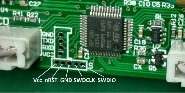
09.06.2023 at 08:35 #4038profi-maxKeymaster
Check the voltage supply to the controller between VCC and GND pins
https://profimaxblog.ru/wp-content/uploads/2021/05/SWD-Pins.jpg
-
-
-
-
07.12.2023 at 20:25 #4116UmkaITParticipant
Приветствую. Огромная благодарность Profi-Max за проделанную работу. Давно слежу за этим проэктом, решил прошить свой DPS5020. Залил (4.4), откалибровал, поюзал, все нравится. Логичный, “вылизаный”, идеально отлаженый софт, придраться не к чему :). Спасибо! Спасибо! Спасибо!
Добавлю пожелание для следующего обновления. Ячейки М и С 10+10 шт. При уменьшении кол. <11 мы теряем ячейки С. Многие все 20 не используют. Логичнее было бы, количество выбирать кратное 2-м. К примеру: 6 в настройках, имеем по 3, М и С, или отдельные настр. для М и С (если место позволяет).
Еще раз Спасибо. Успехов. -
09.12.2023 at 22:58 #4118SerdgParticipant
Добрался я до MPU-6050 (брал по ссылке со странице установки).
Установил модуль MPU-6050, блок DPS5020 видит модуль, но вместо буквы позиции- красный крест.
Что не так? Модуль бракованный? Прошивка 4.4.Подтяжку на линию SCL пробовал 10Ком- не помогло.-
11.12.2023 at 10:32 #4123profi-maxKeymaster
Приветствую. Не могу сходу ответить в чем проблема. Красный крест вместо буквы означает некорректные данные от гироскопа. У меня он отображается, если наклонить девайс на 45 градусов, и девайс оказывается в неопределенном положении.
Кроме этого, можно посмотреть текущую температуру в меню Параметры. Если установлен MPU-6050, она будет браться из MPU-6050. Его можно погреть и посмотреть изменения температуры в меню Параметры.
Могу посоветовать убрать подтягивающий резистор по шине SDA на плате с MPU-6050, так как эта подтяжка есть в самом DPS5020.
См. схему https://profimaxblog.ru/%d1%86%d0%b8%d1%84%d1%80%d0%be%d0%b2%d0%be%d0%b9-%d0%ba%d0%be%d0%bd%d1%82%d1%80%d0%be%d0%bb%d1%8c-%d1%82%d0%b5%d0%bc%d0%bf%d0%b5%d1%80%d0%b0%d1%82%d1%83%d1%80%d1%8b-dps/-
This reply was modified 7 months, 2 weeks ago by profi-max.
-
This reply was modified 7 months, 2 weeks ago by
-
-
10.12.2023 at 09:40 #4119
-
10.12.2023 at 09:42 #4121
-
11.12.2023 at 19:10 #4125SerdgParticipant
Спасибо. температура не меняется при нагреве. Меняется если только греть терморезистор под радиатором.
Подключил параллельно LM75. LM75 реагирует, включает выход при нагреве, включает основной вентилятор.
Значит модуль MPU-6050 пришел бракованный.
У меня вопрос по основному вентилятору: Если сейчас основной вентилятор реагирует на модуль LM75 , то свои функции терморезистор под радиатором не выполняет (не включает вентилятор и не управляет оборотами основного вентилятора при нагреве)?-
11.12.2023 at 19:46 #4130profi-maxKeymaster
Если подключить LM75, то терморезистор под радиатором уже не работает. Я свой LM75 приклеил на термоклей сбоку от радиатора в DPS5020.
Если хотите добавить картинки в этот форум, уменьшайте их размер до 1 мега байта.
Что касается MPU-6050 не спешите его хоронить. Так как я сам не проверял его работу с DPS5020, а только с DPS5005.
Если не сложно, проверьте MPU-6050 со старыми версиями прошивки 3.7 или 3.8, в них не было красного креста, значения с гироскопа шли напрямую.
Я ранее написал ошибочно, что температура берется с MPU-6050. Но это так только для моделей без встроенного терморезистора, типа DPS5005.
Для DPS5020 температура берется с LM75 (если он есть) или с терморезистора, если нет LM75.
Наличие LM75 и MPU-6050 проверяется при старте, до появления экрана с логотипом. Если эти дополнительные модули определились, к версии прошивки добавятся буквы T и/или G соответственно.
На крайний случай, присылайте мне свой MPU-6050, проверю его со своим DPS5020.-
This reply was modified 7 months, 2 weeks ago by profi-max.
-
This reply was modified 7 months, 2 weeks ago by
-
-
11.12.2023 at 19:33 #4126
-
12.12.2023 at 05:49 #4133SerdgParticipant
Откатил прошивку в модуле 5020 на 3,7. Акселерометр система увидела и на дисплее и в меню, но не реагирует
на изменение положения в плоскостях. Возможно это причина того, что ранее я перекатал чип акселерометра
-использовал последний шанс.Attachments:
You must be logged in to view attached files. -
12.12.2023 at 05:54 #4135
-
12.12.2023 at 12:19 #4139
-
12.12.2023 at 12:31 #4141SerdgParticipant
И я почему то думал, что и внутренний терморезистор и 75ый модуль при достижение выставленной температуры
сработают оба. Это было бы сверх удобно, и наверное правильно, так как 75ый модуль мог бы управлять охлаждением блока питания.
Можно в перспективе это реализовать? Просто у меня в перспективе установка TDK lambda PFE1000F-48/T (платы пока в разработке), а у него заявленная рабочая температура +100С. Может и без вентилятора сможет эксплуатироваться, но всё же.-
This reply was modified 7 months, 2 weeks ago by Serdg.
-
12.12.2023 at 17:05 #4146profi-maxKeymaster
1) Срабатывание от двух датчиков реализовать возможно, но думаю, это кроме путаницы ничего не даст. Терморезистор на плате расположен довольно далеко и может показывать не точную температуру, поэтому и нужен LM75. У одноплатных блоков типа DPS5005 вообще нет терморезистора.
2) Все таки в первую очередь надо контролировать температуру выходных транзисторов, а не всего блока. Поэтому LM75 нужно располагать на радиаторе выходных транзисторов.
3) Для дополнительного вентилятора, есть ещё выход у LM75, но он будет срабатывать при тех же 50 градусах.
4) Для дополнительного вентилятора могу посоветовать использовать биметаллический термостат типа KSD9700A. Он будет замыкаться при достижении температуры. Например вот такой:
https://www.avrobot.ru/product_info.php?products_id=6759
-
This reply was modified 7 months, 2 weeks ago by
-
12.12.2023 at 15:40 #4143SerdgParticipant
А RD WiFi плату для RD источников питания можно реализовать взамен Bluetooth?
https://aliexpress.ru/item/4000478822325.html?sku_id=12000036232266981&spm=a2g2w.stores.search_results.1.42425724vbRWrm -
19.12.2023 at 19:32 #4147humaniacParticipant
Hello profi-max,
first of all, thank you very much for your great work and for making it available free of charge.
I have two DPS 5015 which I have flashed to the new firmware 4.4.
Everything worked smoothly with the first DPS 5015.
With the second one I have massive difficulties with the calibration of the output current. Although I have proceeded strictly according to the instructions, a residual current of 0.1 A always remains on the display, even when the output is open.
I have repeated the process several times, also with different hardware versions 1.0 and 2.0. Unfortunately without success. The ADC value for “I out L” looks strange. It always remains at 0, even after repeating the calibration several times.
Do you have any idea where the error may lie?Best regards
PhilipAttachments:
You must be logged in to view attached files.-
20.12.2023 at 18:13 #4155profi-maxKeymaster
Hello Philip,
There may be three reasons.
1. DAC value for IoutL is too small.
2. During the calibration process, the multimeter should be connected to the output terminals when pressing the encoder (when the value turns blue). The ADC value is the output current measured at that very moment.
3. The ADC input of the CPU is faulty.-
20.12.2023 at 20:12 #4156humaniacParticipant
Thanks for the quick reply.
I have also tried various earlier firmwares (4.3 and 3.9). Both with the same result.
I can eliminate point 2 – I was very careful to leave the multimeter connected during calibration.
What exactly does point 1 mean – is there anything I can do?
I’m also afraid it’s a problem with the ADC for the input current.
Could a new STM32 controller solve the problem?Kind regards
Philip-
20.12.2023 at 20:45 #4157profi-maxKeymaster
DAC is the set value for the output. ADC is a measured value.
About point 3. If the ADC for IoutH is not zero after calibration, then the input of the ADC is in order.
About point 1. You can manually change the values of the DAC. As described below.I think that your devices differ only in shunt resistance.
-
20.12.2023 at 21:32 #4160humaniacParticipant
As you can see in the screenshot, the IoutH value of the ADC seems to be determined correctly.
Only the value for IoutL is 0 (sometimes 1 or 2) – in any case unusually small.
Even with a real current measurement, it is close to the correct value. So the ADC seems to be working. Even with no current flowing, 0.10 A is displayed.
I also tried calibrating with different HW versions – it made no difference.
I don’t know where the problem is.Attachments:
You must be logged in to view attached files.-
20.12.2023 at 22:31 #4163profi-maxKeymaster
VALUE ADC
0.104 0This means that during IoutL calibration the ADC current measurement was 0.
During operation this means that when measuring 0 you will see 0.104 amperes on the screen.
The ADC value for IoutL can never be zero.
Even when there is no current at all, the value of the ADC is still more than zero, since there is pulling up resistor at the OA input (R17 3.3Mom).-
21.12.2023 at 15:01 #4164humaniacParticipant
I did some additional voltage-measurements at PIN 17 (PA7) that is the ADC for Current measuerement.
Here are the results:Current Voltage at PA7
0.000 A 0.0000 V
0.104 A 0.0001 V
0.203 A 0.0066 V
0.501 A 0.0404 V
1.003 A 0.0991 V
2.000 A 0.2167 V
5.519 A 0.6309 VLooks like there is a problem with the OpAmp SGM8582 rather than with the ADC of the STM32.
What do you think?-
21.12.2023 at 19:21 #4165profi-maxKeymaster
My measurement at pin 17 (PA7) with DPS5020 stock firmware:
0.00A -> 0.059V
0.01A -> 0.060V
0.1A -> 0.070V
0.5A -> 0.117V
1.0A -> 0.176V
2.0A -> 0.293V
5.0A -> 0.645V
10A -> 1.232V
20A -> 2.400V
The pull-up resistor R17 = 2.7 Mom
Check the pull-up resistor. I think the SGM8582 will not be able to work if the input voltage is less than 0.05V.-
This reply was modified 7 months, 1 week ago by profi-max.
-
This reply was modified 7 months, 1 week ago by
-
21.12.2023 at 19:47 #4166humaniacParticipant
Thank you very much for your efforts!
Did some Excel work with my measured data.
Seems the offset voltage is not correct.
I will check R17 as suggested. Are you sure it is 2.7 MOhm? Thought mine is labeled 3.3 MOhm.
I think, R17 has to be removed for measuring – right?Attachments:
You must be logged in to view attached files. -
21.12.2023 at 20:04 #4168profi-maxKeymaster
The pull-up resistor is just needed to increase the bias voltage on the shunt. Don’t delete it. You can reduce its resistance to 2.5 or 2.7 megohms.
In my DPS5020 R17 = 2.7 Mom -
21.12.2023 at 21:00 #4170humaniacParticipant
Thanks,
I will try this maybe tomorrow and give you some feedback soon.
-
-
-
-
-
-
-
-
28.12.2023 at 15:15 #4174humaniacParticipant
O.K., it took me a little longer to get 2,7 MOhm SMD resistors of size 0603. I finally replaced the resistor and ran the calibration process. The results are better now, but it still shows a residual current of 0.06A even when no current is flowing. The resistor is still too high. Would you recommend trying 2.0 MOhm or even 1.8 MOhm next?
Attachments:
You must be logged in to view attached files. -
02.01.2024 at 16:59 #4178humaniacParticipant
Replaced the 2,7 MOhm resistor now with a 1.8 MOhm type.
That was a success. Calibration was possible without any problems.
Thanks again for your support and a Happy New Year. -
12.01.2024 at 03:17 #4179Spectrum16Participant
Здравствуйте!
Прошил 5015 прошивкой 4.4,все откалибровал,показания верные…
Но есть одно НО, почему-то ограничение срабатывает +100ма. Пример:выставил ток 1а,ограничение 1.100а и светиться синим,а в видео ограничение по току-желтый цвет. Что я не так сделал?-
12.01.2024 at 11:37 #4180profi-maxKeymaster
Приветствую! На видео старые версии прошивок. Должно быть так: в режиме CC цифры синие, а ползунок желтый (ползунок показывает уровень напряжения). В режиме CV всё наоборот.
Если неверно работает стабилизация тока (режим CC), значит прибор неверно откалиброван. Сделайте калибровку ещё раз. При калибровке,в момент фиксации клеммы амперметра должны быть подключены.-
12.01.2024 at 12:05 #4181Spectrum16Participant
Эх,не долго музыка играла…Разобрался с калибровкой,откалибровал токи и входное напряжение собрал в корпус…начал калибровать выходное напряжение и такой звук “пых” и все погасло…Нашел тут схему…померял на стабилизаторах,везде коротыш. Подал 5в там где должно быть 5в и начал искать нагрев-оказалось пыхнула мт3608,съездил купил модуль,сдул микруху и поставил взамен бахнувшей. 5015 запустился,но не выдает напряжение… Точнее,включаешь и очень медленно начинает возрастать…за минуту 0.5в на дисплее и на выходе…В схемах не сильно понимаю, по этому спрашиваю: может кто то сталкивался с таким,что смотреть, или что менять?
-
12.01.2024 at 18:23 #4182profi-maxKeymaster
Сморите тут схему от DPS3003, она во многом совпадает с 5015, вплоть до обозначений элементов.
Питающих микросхем 4 штуки:
Uin -> 5V XL7005A питает всё остальное
5V -> 3.3V HT7133 питание процессора и цифровой части
5V -> 8V MT3608 питает силовую часть в некоторых моделях
8V -> 3.3V M5333B питание аналоговой части SGM582-
This reply was modified 6 months, 2 weeks ago by profi-max.
-
This reply was modified 6 months, 2 weeks ago by
-
-
-
-
12.01.2024 at 19:29 #4184Spectrum16Participant
Все питания на всех стабах-норма! Так как у меня вылетела микросхема делающая 8.4в,то логичнее всего смотреть что она питала,верно? Как минимум 3 элемента связано? Ниже обвел, может можно что то померять на каких то ногах?
Attachments:
You must be logged in to view attached files.-
13.01.2024 at 09:48 #4186profi-maxKeymaster
LM321 служит для формирования постоянного стекающего тока на выходе. Проще говоря для разряда выходных конденсаторов через Q7 и мощный резистор R50. На неё меньше всего подозрения.
TL594 шим-контроллер, формирует шим сигнал с фиксированной частотой 65 кГц и скважностью, зависящей от Uset/Iset и напряжений обратной связи по току и напряжению. На вашей схеме выходной шим-сигнал будет на ножке 10.
LM5106 это драйвер двух выходных силовых транзисторов. В зависимости от уровня входного сигнала (0 или 1 на ножке 8) открывает верхний или нижний выходной транзистор.
Вывод 7 драйвера LM5106 это блокировка, которая полностью отключает выходной силовой каскад транзисторов.
По идее, нужно смотреть осциллографом выходной сигнал TL594, потом смотреть сигнал на затворах выходных транзисторов.
—————
Самая подозрительная тут – это LM5106, так как она имеет высоковольтный вход (ножка 4) от истока верхнего плеча силовых транзисторов.-
This reply was modified 6 months, 2 weeks ago by profi-max.
-
This reply was modified 6 months, 2 weeks ago by
-
-
13.01.2024 at 10:34 #4188Spectrum16Participant
Спасибо вам большое…Я не могу понять, как тут цитировать сообшенив, может в телефоне и нельзя это делать, так что простите заранее.
В принципе все понято, что выше написали…
Заказал кучу деталей,почти все что есть на схеме микросхемы под позиционным обозначением U. Заказал осциллограф))). А ещё записал видео как себя ведет при включении выхода… https://youtu.be/jfxWzUvYD7o?feature=shared
Посмотрите пожалуйста,может видели такое и круг сузится) -
13.01.2024 at 11:17 #4189Spectrum16Participant
А ещё я тупо напряжение измерил…На тл594 на 10 ноге поднимается 6.5В,они же и приходят на лм5106 на 8 ногу…На 7 ноге тл5106 появляется сигнал разрешения напряжением 5.6в,а на затворах тишина,а так же на выходе тл5106(3 и 10) ногах тишина. Понятно что мультиметром-это не замер,но все же. А еще косвенно можно судить что лм321,которая управляет Q7-скорей всего работает т.к выключаешь выход и на затворе Q7 появляется напряжение…
Это были мысли в слух)) Спасибо вам больше.-
This reply was modified 6 months, 2 weeks ago by Spectrum16.
-
This reply was modified 6 months, 2 weeks ago by
-
11.02.2024 at 16:35 #4373ForSmaNParticipant
Приветствую.
dps5020 ревизия платы 2.3 заменил stm32 на новую, память старая осталась.
Пробовал прошивку 4.5 и 4.4, проблема следующая: изо на дисплее перевернуто на 90 градусов, при повороте энкодера значение меняется только в минус, причем при повороте энкодера в любую сторону. Кнопки М1 и М2 поменены местами.
Если войти в меню поворота дисплея картинка становится нормальной, параметр поворот стоит в значении да, меняю на нет результат прежний… изо 90 градусов перевернуто. В чем может быть дело ? Шил через st-link v2 Китайский, cube его не видит серийник, использовал ст-линк утилит.-
11.02.2024 at 17:03 #4374profi-maxKeymaster
Здравствуйте!
По энкодеру похоже на замыкание. Проверьте нет ли замыкания между пинами энкодера. Они рядом на процессоре BTN_ROT_A и BTN_ROT_B.
Распиновка тут: https://profimaxblog.ru/%d0%ba%d0%b0%d0%ba-%d1%80%d0%b0%d0%b1%d0%be%d1%82%d0%b0%d0%b5%d1%82-%d0%bf%d1%80%d0%be%d1%88%d0%b8%d0%b2%d0%ba%d0%b0-dps/
Если с помощью меню поворота (пункт Position) вы можете добиться нормального положения и это положение сохраняется в памяти, то ничего страшного. Возможно, у вас немного другой дисплей.
Если не происходит запоминание в меню поворота после Save?=Yes и Exit возможно НЕ сохраняется в памяти EEPROM.
Проверьте работу EEPROM изменив значения в меню Profile. Если EEPROM работает, то новые значения будут и после отключения питания.
-
-
11.02.2024 at 19:41 #4375ForSmaNParticipant
Энкодер не замкнут, но на одной ноге есть 3.3v, а на другой нет. Я так понимаю нету внутренней подтяжки у stm32.
История этой платы следующая… на плату попал шарик припоя и что то закороти, в итоге у stm32 пин отвечающий за М2 просто ушел в кз на землю, пришлось менять STM.
Не как не могу понять, схема разводки кнопок М1 и М2 совпадает с Вашей, но при нажатии М1(V) нажимаются амперы на дисплее и наоборот.Attachments:
You must be logged in to view attached files.-
11.02.2024 at 20:04 #4378profi-maxKeymaster
Кнопки меняются местами вместе с поворотом экрана.
Поворот экрана храниться в EEPROM и считывается в самом начале запуска прошивки, до отображения экрана заставки, чтобы заставка корректно отображалась.
Поворот не отменяется через меню Restore Default и не отменяется при смене прошивки.
Изменить поворот можно только в меню Rotation.Пины энкодера BTN_ROT_A и BTN_ROT_B подтянуты к 3.3 вольтам самой прошивкой внутренними резисторами процессора. Если у вас на одном из этих пинов ноль, значит он замкнут на землю.
Сюда на форум можно загружать фото размером до 1 МБайта.
-
-
11.02.2024 at 19:45 #4377ForSmaNParticipant
Фото на Ядиске https://disk.yandex.ru/d/Ujoiq6Pui6Qs4Q
-
11.02.2024 at 20:19 #4379ForSmaNParticipant
Так докладываю… разобрался.
Всему виной не внимательность. Плохо посадил STMку и некоторые пины не контачили, в том числе и с EEPROM.
Еще раз все хорошо прогрел с флюсом и все заработало.
Кнопки поменялись местами в месте с поворотом дисплея.
Появилась подтяжка на пине энкодера.
Огромное спасибо Автору данного проекта, помог оживить БП.-
28.02.2024 at 17:40 #4515Spectrum16Participant
Здравствуйте ещё раз всем!
Эпопея продолжается…Пришли мне все приборы и запчасти….Один 5015 починил полностю,а со вторым есть нюансы,он первых ревизий, схема отличается,а точнее номиналы компонентов, видимо производитель пересмотрел их.
Теперь собственно вопрос:
За что отвечает этот узел?(во вложении отмечен будет).У меня там тоже все бахнуло Q6 и его обвязка и операционник U6.. Щас имею такую проблему… Все работает,регулируется,ток ограничивает,но при выключении очень и очень медленно падает напряжение, можно сказать вообще не падает…Операционник я перепаял,еще в бесконечности был (по видимому R39),но маркировка странная у него,может кто знает что это за резистор такой может это 100(10 Ом)? Там вообще все номиналы другие (R40,R42) не такие как на схеме. Я поставил как на схеме 20 Ом, стало после выключения падать напряжение,но медленно, где то за минуту…
Из опытов я понял, что когда у 5015 выключен выход Q6 открыт и как раз через него выход подтягивается к минусу и это правильно?
В общем подскажите что нить, пожалуйста?-
This reply was modified 4 months, 4 weeks ago by Spectrum16.
-
This reply was modified 4 months, 4 weeks ago by Spectrum16.
Attachments:
You must be logged in to view attached files. -
This reply was modified 4 months, 4 weeks ago by
-
-
29.02.2024 at 18:23 #4521Spectrum16Participant
Спасибо большое…А может такое быть, чтоб не было Q7? Смотрел в упор,но не нашел такого. Радиатор снят, если что…у меня 4 силовых мосфета по два в паралель… Видел кто нить такое?
-
29.02.2024 at 18:31 #4522Spectrum16Participant
Вот фото платы…Один отпаян,сгорел
-
This reply was modified 4 months, 4 weeks ago by Spectrum16.
Attachments:
You must be logged in to view attached files. -
This reply was modified 4 months, 4 weeks ago by
-
01.03.2024 at 15:44 #4525profi-maxKeymaster
Наверно у Вас другая схема
-
-
04.03.2024 at 13:10 #4526maviParticipant
Здравствуйте
Спасибо за ваш труд
Есть ли возможность снять ограничение по току у 5020 до 35А.-
05.03.2024 at 09:04 #4527profi-maxKeymaster
Здравствуйте!
Программную часть переделать на 35 ампер возможно. А вот с аппаратной частью – не уверен…
Давайте подумаем что для этого нужно:
Увеличить ток силовых транзисторов в 2 раза. Расположить их на внешнем массивном радиаторе с обдувом. Восемь транзисторов вместо четырех. Неизбежно ухудшиться КПД, нагрев возрастет.
Другой дроссель. Нужно увеличивать сечение магнитопровода и сечение проводов в дросселе. Желательно в 2…4 раза. Заводской дроссель 5020 уже сделан по минимуму и при длительном выходном токе 20 ампер перегревается и снижает индуктивность. Его для длительного тока 20 ампер уже нужно менять.
Обратная связь по току. Нужна переделка, уменьшение напряжения обратной связи по току в 2 раза.
-
-
06.03.2024 at 19:21 #4528maviParticipant
Спасибо за разъяснения.
Про обратную связь по току я не учел.
Выходные и дроссель не проблема.
Был давно переполюсован выходной каскад заменён на другие в то220 с большим запасом.
Спасибо за ответ -
14.04.2024 at 21:48 #4563orevParticipant
Здравствуйте!
Мастер, благодарю за ваш труд! Очень достойная работа!Использую один из DPS 5020 совместно с батарейным блоком как портативный блок питания(для путешествий,рыбалки,охоты и т.д.)
Возможно ли сделать на уровне прошивки(без добавления дополнительного блока) контроль разряда, чтобы DPS отключался при заданном-минимальном напряжении на входе, для сохранения годности аккумуляторов?-
This reply was modified 3 months, 1 week ago by orev.
-
15.04.2024 at 09:59 #4565profi-maxKeymaster
Приветствую. Спасибо за оценку.
При питании от батареи, включите в меню опцию Battery source. В этом случает на экране будет отображаться уровень заряда батареи. При попытке включения нагрузки при низком заряде батареи будет выскакивать ошибка BAT.
Изначально настроено для батареи из 10-ти литиевых элементов (минимальное напряжение 30 вольт, максимальное 42 вольта). Если у вас другая батарея, то нужные минимальное и максимальное напряжения можно задать с помощью программы DPSmaster.
Полное отключение при низком разряде в самом DPS сделать невозможно, так как нет таких ключей, которые бы отключали питание.
НО.. если вы используете батарею из литиевых элементов, то эта батарея должна быть оборудована блоком BMS. А блок BMS защищает не только от большого тока, но и от переразряда. То есть правильный блок BMS будет полностью отключаться при низком заряде батареи.
Найти правильный BMS достаточно сложно. Большинство BMS отключаются, когда напряжение на одном элементе снижается до 2.5 вольт. А хотелось бы 3.0 вольт. Тем не менее, это работает. Я сам лично использую батарею из 10-ти литиевых аккумуляторов и BMS от самоката.
Вот пара статей про BMS:
https://e-solarpower.ru/faq/vse-ob-akkumulyatorah/sistema-upravleniya-batarei-bms/
https://habr.com/ru/companies/timeweb/articles/708196/
-
This reply was modified 3 months, 1 week ago by
-
15.04.2024 at 10:28 #4566
-
22.04.2024 at 07:16 #4628mmmmdanoneParticipant
Потестил фирмварь 4.5, замечательно работает, респект автору!
“Но есть один нюанс” ©
У меня БП DPH5005 — это тот который с повышающим преобразователем на входе.
(схема есть на circuit maker com, Projects/Details/Damian-Thompson-2/DPH3205-Reverse)Соответственно, МК измеряет входное, которое может быть меньше повышенного. Повышенное всегда 54в (в моем случае)
Получается, когда я пытаюсь выставить 50в на выходе и питаю БП от 24 срабатывает защита по низкому входному.Не большая проблема, но было-бы клево сделать отключаемой защиту по низкому входному.
А буст на входном очень удобен в машине, где есть только 12 вольтб и надо например питать ноутбук. -
23.04.2024 at 17:59 #4630iuraParticipant
DPH5005 – Залил работает шикарно.
USB – работает, но WIFI не хочет(esp32 и esp-07s).
Жду с нетерпением обнову, автору респект-
23.04.2024 at 19:42 #4631profi-maxKeymaster
Постараюсь на днях сделать прошивку для DPH5005, при наличии свободного времени.
Вы говорите про WiFi. Имеется ввиду модуль из моего проекта на гитхаб?
https://github.com/profi-max/DPS_WiFi_module
Какие именно сложности c Wifi? Прошивка заходит? Подключение к роутеру работает? DPSmaster соединяется с модулем?
-
-
24.04.2024 at 09:53 #4632iuraParticipant
Прошил с гида(https://github.com/profi-max/DPS_WiFi_module) – модуль запустился. Выбрал сеть. По рутору определил IP
Attachments:
You must be logged in to view attached files.-
24.04.2024 at 11:13 #4637profi-maxKeymaster
Проверьте как соединяется DPSmaster по TCP и IP адресу.
Если пишет “The TCP server at XXX.XXX.XXX.XXX does not reply” значит вообще не находит IP адрес.
А если пишет “Timeout when receiving data”, значит соединение установлено, но нет связи между DPS и ESP8266.
Проверьте, включен ли WiFi в меню Communication блока питания. Проверьте скорость, должна быть 115200.
-
-
24.04.2024 at 13:11 #4638iuraParticipant
Поменял 10к на 5,1к gpio15 и перезалил скейч. Всё заработало
-
01.05.2024 at 16:09 #4653iuraParticipant
Залил прошивку на DPH5005 – все работает.
Буду тестить -
18.05.2024 at 00:12 #4696aladarrParticipant
I have dps8005, update to firmware 4.5 and when I try to use it I get after some time :
OHP icon on display and power is cut.
OHP – Overheat temperature.
I hase set the temperature in menu to 85
I have proper cooling, and I get under 23 degrees .
Why is this OHP triggered ? and how can I stop it or have a fix ?Befere I have updated to firmware 4.5 , with stock firmware, all was good , no problems at all.
-
18.05.2024 at 08:31 #4697
-
-
18.05.2024 at 11:40 #4699aladarrParticipant
that temperature is about 25-30C, with a fan active and cooling the unit/case this temperature is about 14C which is a little too low considering I have 23C in my room. This is weird.
When the power supply is in use, after a couple of minutes, I enter in the menu and the temperature is 65C.
i set the temperature to 95C OHP and now it will not stop based on OHP.
Is it bad? not recommended to set OHP at 85C or even more, until my power supply can work continuously without triggering OHP.? -
22.05.2024 at 20:37 #4701aladarrParticipant
found this :
https://www.kirich.blog/obzory/bloki-pitaniya/623-reguliruemyy-dc-dc-preobrazovatel-dps8005-usb-bluetooth.htmlНо я бы не сказал что температуры совсем низкие, после примерно 20-25 минут работы на мощности 200-250 Ватт я получил такие значения:
Транзистор – 92 градуса
Диодная сборка – 88 градусов
Дроссель – 65 градусов.it looks like these are the normal temperatures to work.
Thank you all for all the good work. -
23.05.2024 at 17:44 #4702LexParticipant
Hello, Can someone help me? I am stuck trying to update my new DPS3005.
See pictures. STM Programmer cannot read from my ST-Link but appears to have erased it successfully !?Здравствуйте, может кто-нибудь мне помочь? Я застрял, пытаясь обновить свой новый DPS3005.
Смотрите фотографии. Программатор STM не может прочитать информацию с моего ST-Link, но, похоже, успешно удалил ее!?Attachments:
You must be logged in to view attached files. -
26.05.2024 at 16:35 #4706DemiurgeParticipant
День добрый, попробовал обновить прошивку на своём DPS5020 на 4.5, всё в точности по мануалу и как на видео, но в конце дисплей так и не засветился, при чтении записанного видно что всё есть, пробовал прошивать более ранние версии 4.4 и 4.3, бес толку, результат тот же.
-
27.05.2024 at 08:54 #4707profi-maxKeymaster
Здравствуйте! Первый раз с таким сталкиваюсь.
1) Проверьте пин 7 (NRST) микроконтроллера, не замкнут ли он на корпус. Этот пин ещё есть на разъёме для прошивки.
2) Проверьте напряжения в цепи подсветки экрана. Пин контроллера 43 (PB7) примерно 2.7 вольта идёт на резистор R27, затем на базу транзистора Q3. На базе Q3 примерно 0.56 вольта. На коллекторе Q3 примерно 0,2 вольта и далее через разъем на подсветку дисплея.-
27.05.2024 at 17:50 #4708DemiurgeParticipant
NRST в порядке, по крайней мере на землю и 3.3V не коротит, а вот сигнала на 43 выводе контроллера нет, на колекторе G3 2.5V
Возможно вы меня неправильно поняли, блок в принципе не подаёт никаких признаков жизни, хотя до этого с китайской прошивкой всё работало исправно, сомневаюсь что проблема апаратная.
По началу я не мог перепрошится в принципе, вылетала ошибка, вроде бы по стиранию памяти, после я отключил блок питания, подключил 3.3V через разъём программирования и всё прошилось, с другим блоком питания тоже проблем не возникло так что грешу на тот БП что стоял изначально, не уверен могло ли это повлиять на корректность перепрошивки.-
27.05.2024 at 21:33 #4709profi-maxKeymaster
Ну смотрите, если процессор не сгоревший, если он не находиться в режиме BOOT (в режиме программирования прошивки), если подано питание и был сделан RESET в момент подачи питания, он должен запуститься.
У меня никогда не было необходимости подавать внешнее питание 3.3 вольта через разъем программирования.
Начните всё сначала, без внешнего питания прошейте процессор. Выставите все нужные галочки:
RDP на странице OB – снимает защиту от чтения у китайской прошивки.
Начальный адрес 0х8000000.
Verify progremming – проверка правильности после прошивки.
Run after programmin – запустить процессор сразу после прошивки.
Вот мой лог сразу после подключения ST-Link:
22:26:56 : ST-LINK SN : 44005700100000345233544E
22:26:56 : ST-LINK FW : V2J44S7
22:26:56 : Board : —
22:26:56 : Voltage : 3.25V
22:26:56 : SWD freq : 4000 KHz
22:26:56 : Connect mode: Normal
22:26:56 : Reset mode : Software reset
22:26:56 : Device ID : 0x420
22:26:56 : Revision ID : Rev Z
22:26:56 : UPLOADING OPTION BYTES DATA …
22:26:56 : Bank : 0x00
22:26:56 : Address : 0x4002201c
22:26:56 : Size : 8 Bytes
22:26:56 : Bank : 0x01
22:26:56 : Address : 0x1ffff800
22:26:56 : Size : 16 Bytes
22:26:56 : UPLOADING …
22:26:56 : Size : 1024 Bytes
22:26:56 : Address : 0x8000000
22:26:56 : Read progress:
22:26:56 : Data read successfully
22:26:56 : Time elapsed during the read operation is: 00:00:00.006-
28.05.2024 at 18:59 #4710DemiurgeParticipant
Прошил чисто на питании от программатора, прошивка прошла успешно, по крайней мере в догах н каких проблем я не увидел, но при подаче питания блок всё так же не подаёт признаков жизни, после прошил ещё раз но уже от питания двенадцати вольтовым аккумулятором, результат тот же.
Возможно я чего не доглядел, вот мои логи.
18:41:21 : UR connection mode is defined with the HWrst reset mode
18:41:22 : ST-LINK SN : 411303013212354D434B4E00
18:41:22 : ST-LINK FW : V2J29S7
18:41:22 : Board : —
18:41:22 : Voltage : 3.19V
18:41:22 : SWD freq : 4000 KHz
18:41:22 : Connect mode: Normal
18:41:22 : Reset mode : Software reset
18:41:22 : Device ID : 0x420
18:41:22 : Revision ID : Rev Z
18:41:22 : Debug in Low Power mode is not supported for this device.
18:41:22 : UPLOADING OPTION BYTES DATA …
18:41:22 : Bank : 0x00
18:41:22 : Address : 0x4002201c
18:41:22 : Size : 8 Bytes
18:41:22 : Bank : 0x01
18:41:22 : Address : 0x1ffff800
18:41:22 : Size : 16 Bytes
18:41:22 : UPLOADING …
18:41:22 : Size : 1024 Bytes
18:41:22 : Address : 0x8000000
18:41:22 : Read progress:
18:41:22 : Data read successfully
18:41:22 : Time elapsed during the read operation is: 00:00:00.008
18:41:26 : MASS ERASE …
18:41:26 : Mass erase successfully achieved
18:41:26 : UPLOADING …
18:41:26 : Size : 1024 Bytes
18:41:26 : Address : 0x8000000
18:41:26 : Read progress:
18:41:26 : Data read successfully
18:41:26 : Time elapsed during the read operation is: 00:00:00.008
18:41:30 : Memory Programming …
18:41:30 : Opening and parsing file: FW5020_V45.bin
18:41:30 : File : FW5020_V45.bin
18:41:30 : Size : 61.24 KB
18:41:30 : Address : 0x08000000
18:41:30 : Erasing memory corresponding to segment 0:
18:41:30 : Erasing internal memory sectors [0 61]
18:41:31 : Download in Progress:
18:41:34 : File download complete
18:41:34 : Time elapsed during download operation: 00:00:03.933
18:41:34 : Verifying …
18:41:34 : Read progress:
18:41:34 : Download verified successfully
18:41:34 : RUNNING Program …
18:41:34 : Address: : 0x08000000
18:41:34 : Application is running, Please Hold on…
18:41:34 : Start operation achieved successfully-
28.05.2024 at 20:14 #4711profi-maxKeymaster
Судя по вашему логу, ваш процессор и прошился и запустился после прошивки успешно: Application is running, Please Hold on… Start operation achieved successfully
-
29.05.2024 at 18:23 #4712DemiurgeParticipant
Выходит проблема точно не программная, и в какую сторону тогда можно копать?
-
29.05.2024 at 18:50 #4713profi-maxKeymaster
Процедура стандартная:
1) Убедиться что на процессор поступает питание.
2) Убедиться, что процессор не находиться в режиме программирования. По уровням на ножнах BOOT и NRST.
3) Убедиться, что на дисплей поступает питание.
4) Попробовать засветить подсветку дисплея, перемкнув коллектор транзистора Q3 на корпус. Убедиться, что подсветка работает.
5) Посмотреть осциллографом сигналы идущие на дисплей. Есть ли там импульсы. -
09.06.2024 at 15:46 #4714DemiurgeParticipant
1) Питание на процессор поступает 3.35V.
2) На BOOT и BRST напряжение отсутствует.
3) Питание дисплея аналогичное что и у процессора 3.35V.
4) Подсветка работает исправно, замкнул транзистор G3 и экран засветился белым, никаких изображений на нём не появилось.
5) На данный момент под рукой нет осциллографа, мультиметр показывает скачки напряжения на линиях данных дисплея, из этого делаю вывод что сигналы есть.
В конце месяца смогу потыкать осциллографом, но пока снова захожу в тупик, не вижу никаких причин почему оно не должно заработать. -
09.06.2024 at 22:18 #4715profi-maxKeymaster
Замерил на своей плате DPS5020. BOOT – 0V, NRST -3.3 V
Судя по фото отсюда https://profimaxblog.ru/dps-pcb-photos-and-schematic/
ножка NRST никуда не подключена. Так как внутри процессора есть собственная схема RESET. Похоже она у вас не исправна, можно попробовать подать на ножку NRST напряжение 3.3 вольта через резистор 5,1 кОм.
-
-
-
-
-
-
-
-
-
AuthorPosts
- You must be logged in to reply to this topic.
This Post Has 5 Comments
Comments are closed.
Большое человеческое спасибо за DPS3003
Пожалуйста)
С выхода регулятора ставим дроссель 3,2-3,6 мкгн, за ним электролит, микрофарад на 10. Далее схему на двух транзисторах IPB017N06N3
и LTC4372. LTC4372 запитываем отдельно- от регулятора. Обратную связь переделываем на выход защиты и дублируем на случай обрыва резистором.
Или, если нет падения через транзисторы, то лучше обратную связь установить за дроссель. А параллельно дросселю установить резистор 47 Ом.
Но установить этот аварийный резистор на случай обрыва цепей обратной связи на самой плате регулятора.
Это самый эффективный вариант защиты и от переполюсовки и от обратного напряжения и от пропадания питания.
A great job you’ve done!
Thanks